Description.
This voltage regulator circuit can deliver up to 3A at 12V output voltage. The circuit can be employed on occasions when a current of more that 3A is demanded for regulator. IC regulators of such high current rating are pretty hard to find.
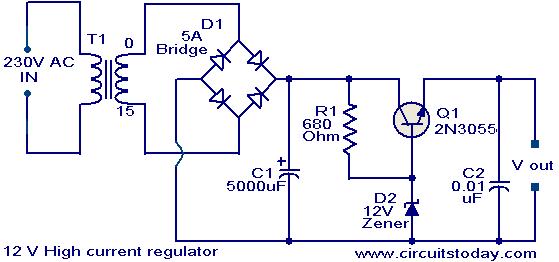
The transformer T1 steps down mains voltage, to 12rms & the rectifier bridge D1 rectifies it to produce a DC voltage. The C1 filters the rectifier output and produces a DC level. The series pass transistor Q1 (2N 3055) is biased by resistor R1 (680Ω). Since zener diode D1 is under breakdown region the voltage across it will be 12V. So the total output voltage will be steady 11.3 V(theoretically). That is the zener voltage minus base emitter voltage of Q1.Here transistor Q1 will conduct the excess current required .
Circuit diagram with Parts list.
Notes.
- Assemble the circuit on a good quality PCB or common board.
- If 12V zener is not available ,use the nearest value.
- The transformer T1 can be as 23oV primary;15V/5A secondary step down transformer.
- The capacitors must be rated at least 25V.
- By changing the value of the Zener diode, different output voltages can be obtained from the circuit.
16 Comments
Hi
I need an electronic circuit that controls constant current regulator voltage and the amper from 0 volts dc to 10 volts dc and from 0 amps to 10 amps
sir, can get a copy of how you designed the circuit along with the description and working
sir give me the pcb design circuit of 12v high current regulator…plz
I design a power supply using bridge rectifier which regulate voltage 5v
your circuit is very good . Sir, I need constant current source using 8pin IC for driving HB led of 1watt & string of such three LED’s. pls. suggest circuit. Also mail circuit diagram of PWM solar charge controller.
Thank you.
pls i need information 4 the design and construction of a 12v regulated power supply.
I design a circuit of regulated power supply which regulate voltage from 1.25 to 33 and current is 1.5
I’d like to know following things.
1) how much maximum output(voltage and current) can stepper motor (of Dot matrix printer)gives if we run it with some driving device.
2) I’d like to use that motor output to run small capacity invertor say of 100w
I already modified some windings of that motor and got 28 volt max current.Could you please suggest me any ckt which can do pure DC of stepper motor then store it in battries then to invertor ckt and then finally AC 230 volt of 100w
Thanks for the simple circuit. The out put will be 12V minus BE drop of 2N3055, that 11.3volt. To make it 12Volt I used one number 1N4007 in series with D2. To make the reference as 12.7 volt to get 12volt output. In operation above 1Amp load current the voltage started dropping hence I added a CL100 (Any medium power high gain NPN transistor will do) as darlington to 2N3055. This solved the problem at 4Amps load current.
Hi Seetharaman, V.S. I would like get Variable amp and variable amps(Upto 6 Amp) from the above circuit. So Will you plz guide me about the schematics required for it. I build the circuit using 6.2Volt Zener for an output of 5.6 volt. At load the voltage dropped to 5.35 volts at 1.5 amps. The 3055 got very hot barely able to touch it. SO Will you plz provide me with the necessary schematics so that I can adjust the voltage and current. It should act as a current limiter aswell.
Hi Seetharaman, V.S. I would like get Variable amp and variable amps(Upto 6 Amp) from the above circuit. So Will you plz guide me about the schematics required for it. I build the circuit using 6.2Volt Zener for an output of 5.6 volt. At load the voltage dropped to 5.35 volts at 1.5 amps. The 3055 got very hot barely able to touch it. SO Will you plz provide me with the necessary schematics so that I can adjust the voltage and current. It should act as a current limiter as well.