Description.
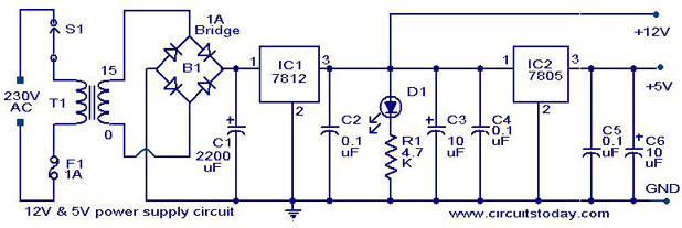
This is a simple approach to obtain a 12V and 5V DC power supply using a single circuit. The circuit uses two ICs 7812(IC1) and 7805 (IC2) for obtaining the required voltages. The AC mains voltage will be stepped down by the transformer T1, rectified by bridge B1 and filtered by capacitor C1 to obtain a steady DC level .The IC1 regulates this voltage to obtain a steady 12V DC. The output of the IC1 will be regulated by the IC2 to obtain a steady 5V DC at its output. In this way both 12V and 5V DC are obtained.
Such a circuit is very useful in cases when we need two DC voltages for the operation of a circuit. By varying the type number of the IC1 and IC2, various combinations of output voltages can be obtained. If 7806 is used for IC2, we will get 6V instead of 5V.Same way if 7809 is used for IC1 we get 9V instead of 12V.
Circuit diagram with Parts list.
Notes.
- Assemble the circuit on a good quality PCB or common board.
- The transformer T1 can be a 230V primary, 15V secondary, 1A step-down transformer.
- The fuse F1 can be of 1A.
- The switch S1 can be a SPST ON/OFF switch.
- The LED D1 acts as a power ON indicator.
- If 1A bridge B1 is not available, make one using four 1N4007 diodes.
- 78XX series ICs can deliver only up to 1A output current.
43 Comments
Can you please help me. What’s the schematic diagram for a PS that has 2 outputs (25 volts and 14 volts). How can or what components should I add to generate a output from this schematic. As iwant to use this PS for Audio Amplifire
A reply will be much appreciated thank you!
Hi what is the watt of the resistor used? Also the voltage in each capacitors. Thank you.
hi can I have a circuit with 5v and 12v output 2A
Can you please help me. What’s the schematic diagram for a PS that has 3 outputs (12, 5 and 3.3 volts). I know this is already 12 and 5 volts, how can or what components should I add to generate a 3.3 volts output from this schematic. A reply will be much appreciated thank you! 🙂
I made your circuit. I have little problem that is the output voltage at the 12V drops to 7.07V after some time without even applying any load.Do you know what may be causing this time dependent problem.
can i get the PCB lay out. i would like to build it
Will this ciruit be able to power a desktop hard drive?
hi! do you have a layout diagram of this? can I have it right now?
hi! can I use a transformer with a lower current rating? and if it is possible, is there any difference if I used 750 or 500mA instead of 1A transformer? please help me. I need a 12v dual power supply for an ASK modulator…thank you in advance 🙂
Hi Taiwo please go through our earlier circuits on this,
https://www.circuitstoday.com/5v-power-supply-with-overvoltage-protection
Pls I need a design of a power supply that has an input of 220v with an output of 5v direct voltage. Pls reply.
Please help me ! 🙂
i want to generate -5v and -12v from this circuit what will be the suitable modification ??
HI omer use 7912 and 7905. Interchange the input supply leads to 7912.
12-0-12 v ac to 5vdc converter diagram send to mail
PLS HELP ME TO DESCRIBE THE LIMIT OF 5V-12V CIRCUIT OPERATION
I try to build like yours. what happened if i switch to configuration of led and resistor. resistor afterthat led. and what kind of led color do you use?
hi, at home i found two hdd’s 3.5 inches
the two ones are:
a) Maxtor Diamond Plus 9 80 GB ATA 133 HDD
+5 Volt 0,670 Ampere
+12 Volt 0,960 Ampere
b) Maxtor Fireball 3 40 GB ATA 133 HDD
+5 Volt 0,559 Ampere
+12 Volt 0,601 Ampere
I bought one controller to convert from IDE to USB, and on the circuit the flat for the HDD was not weldered, so i change it with one flat more long for IDE for
2 HDD’s.
Now the problem, i can’t use it’s own power supply for the simple fact that is not so big to grant so much power:
the specs of the power supply
240 V / 12 Volt
+5 Volt 1,5 Ampere
+12 Volt 1,5 Ampere
I would to change with another one (switch) normally used for the computers for the simple fact that the flat for 12 and 5 Volt is not weldered on the circuit
and it’s possible to connect to another power supply, respecting only +5 Volt and
+12 Volt.
can i use a power supply ATX 500 WATT to 240 Volt ?
VOLTAGE CURRENT FREQUENCY
110V 12A 50-60Hz
220V 6A
ORANGE YELLOW BLUE RED WHITE PURPLE
+3.3V +12V -12V +5V -5V +5Vsb
14A 30A 0.5A 20A NP 2.0A
NP = No Present
awating your reply as soon as possible,
greetings,
paul
p.s: happy hacking 😉
pls.email me..is 15V 3A transformer applicable in this circuit?? is the output the same???
Hi nhoy You have to use only 15 volt 1 amp rating transformer as the rectifiers can handle only 1amp max.
actually i want to generate a 12V 15A power supply with pulse rate of 3ns without using a transformer…
please reply if any1 can help
Hey. If i donot want to use transformer and the specs are 12V and 15A current with 3 nanosec what would i use instead of a transformer and how?
Please Please reply soon…
Hi Huma cannot be done.
i tried to develop the PCB layer of circuit above but i got wrong output you can help PCB layer of that circuit
If i was to use 110VAC as the input, would i only need to change the transformer out? If so what would it need to be or what parts would need to change?
reply to Michael
yes you need to change the transformer only.
Thanks for the information and helpful schematic diagram. I understood the operation briefly. I will use this power supply module to provide +5V for the 8-bit input generator and +12V for the A/D that uses ADC0804. Our project is to make an experiment board in instrumentation and control through the PC parallel port.
Hi Manish if you do not want indication you can omit LEWD and associated resistance.
You have to use all the indicated capacitors as they are important to take care of decoupling the power supply for low as well at high frequencies. it is not for the reason that author could not get 10.1uF. Normally electrolytic capacitors are -20 to +50% tolerance types. Electrolytic capacitors are wound type hence they have inductive component also in them to take care of it, in decoupling, a disc capacitor which is non inductive also used in parallel, this is very important when you use the supply for energizing digital circuits.
dear sir,
if i am not using the led, can i omit the resistor?. Also can i replace the 3 capacitrs aftrt 7812 with a single one,if yes wat diference vl it make.
hi,type of c1,c3,c6(how much voltage must use)please??
Hi Bulgaa The simplest protection will be fix a 13volt zener diode in the 12volt output and 5.6volt zener in the 5 volt output.
Can u make over-voltage protection on this diagram. asap
Hi Bithika these circuits are meant for 230 + or – 10% input supply. hence it will work from 200 to 250 volts.
can it be used for 220vac input and why?
Is it okay to use a 220vac input instead of the 230vaC?
Hi Ramakrishna High current supplies cannot be constructed with capacitors. they will be suitable for low current say upto 100mA only. for higher current try to use switched mode power supplies. they are quite efficient. on the long run you will save lots of energy greener planet.
hi,
im rama krishna, can we built the ckt with same ratings without using transformer
Hi Santhosh how a single diode will drop 7 volts it can drop just 0.7 volt. you require 10 diodes to drop it to 5 volts.
if u want to reduce the power dissipation on 7805 u can use series of diode 1n4007 just b4 the regulater it will drop the voltage from 12 v to 7 v(i have not tried it yet try it at ur own risk)
the power dissipation will be 12v-5v* 400mA
wn u see + symbol in th diagram it is understood it is electrolytic the others are ceramic
hi,type of (0.1uf)c2,c4,c5(electrolytic or ceramic)please??
thanks
I’m guessing the 7805 IC will need a heat sink if you pull say 400mA.
15V – 5V = 10V (voltage reduced)
10V * .400mA = 4W (power to dissipate)
plz email me.. is this circuit apllicable with a 220v ac input and 12v output transformer? plz need response…
Can also this Power Supply happen to have a 220V AC Input??