Description.
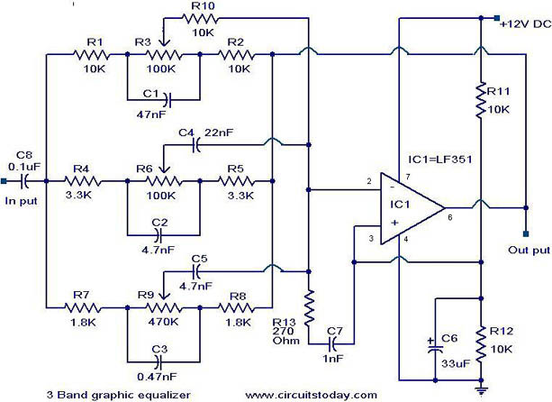
Here is a simple 3 band graphic equalizer circuit made of a single op amp IC LF351 (IC1) and few passive components.The component values of this circuit are not very critical and can be replaced with nearest values with a little loss on the performance.This feature make it easy to be assembled from your junk box.
The opamp LF351 is wired to operate in three frequency ranges- high,medium and low.The circuit is designed such that the circuit produces +/-20 dB boost or attenuation for 50Hz,1KHz and 10Khz by varying POT’s R3, R6 and R9.The maximum amplification for any of these bands at maximum supply voltage is 20dB.The opamp LF 351 is wired as an inverting amplifier whose response to frequencies 50Hz,1Khz and 10KHz can be varied by adjusting POT’s R3,R6 and R9.
Circuit diagram with Parts list.
Notes.
- The circuit can be operated from 6 to 24 V DC .What I recommend is 12V .
- Use a 12V battery or 12 V DC power supply for the circuit.
- All capacitors must be rated 15V.
- A 10uF/15V capacitor must be connected between +ve and -ve pins of LF351 if the power supply is far from the circuit.Not shown in circuit.
14 Comments
Hello
What is the name of filter system used in the circuit? (For example Sallen-Key)
Thanks
That interest mee too! 🙂
hello admin! what components do you recommend if I want to build this EQ with a frequency maximum of 5KHZ?
hello sirs..
Can this circuit process stereo input and give stereo output?
hello sir
can u please provide details about its working
Hi Davis you can use TL061, 71 or 81
Sir I don’t get the ic LF351 in the market.Is there any substitute for it
Sir I don’t get the ic LM351 in the market.Is there any substitute for it
lm741 should work fine
Hi there, could you possibly tell me the formulas to calculate the different frequencies?
Thankyou
Oh, and another question:
How is the EQ-band frequencies calculated given the component values?
How is the input audio signal biased correctly? Should you just leave the pins 1 and 5 (offset/null) unconnected on IC1?
What is the 10uF/15V capacitor is good for and why it has to be connected only if the power supply is far from the circuit?
the job of this capacitor is filtering and noise reduction (capacitor by passes high frequencies, making the DC supply more pure). If the power supply is very far away from the circuit , the supply wires may catch stray noises from the surroundings and this cannot be corrected by the filter and decoupling capacitors inside the power supply circuit.The capacitor connected across the supply lines will by pass these induces noises, making the circuit perform better. Any way this is just an extra precaution and there wont be much problem in the practical performance of the circuit even if you don’t use this capacitor.