Description.
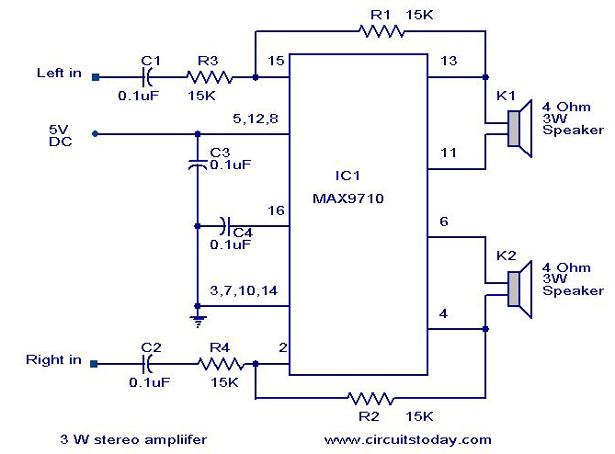
A straight forward circuit diagram of a 3W stereo amplifier circuit using MAX 7910 IC is given here. This circuit is ideal for small power audio applications like portable CD players or radio sets. The circuit is designed strictly as per the datasheet and found to be working great.
The MAX9710 a stereo audio power amplifier IC capable of delivering 3Watts of out put to 4 Ohm loads. MAX9710 can be operated from a single 4.5V to 5.5V power supply, makes it ideal for hand held applications. The IC also features thermal overload protection.
Circuit Diagram with Parts list.
Notes.
- Use a 5 V DC power supply for powering the circuit.
- If you want to use a battery ,then use a 6V battery with a IN 4007 diode series to the positive terminal of it.The diode will drop 0.7 V and the IC will get the rated ~5V.This is just a saftey recommendation .
- Assemble the circuit on a good quality PCB or common board.
4 Comments
what is the frequency response range for this IC .?
It appears that each channel has a voltage gain of only 2, so if you want any gain, you’ll need to increase the value of R1/2 to maybe 150K or more. Also, C1/2 roll off the low response at 100Hz, so you may want to use .5mF to improve bass.
Hi Valentinas the 6th page of the datasheet gives you full details
http://www.datasheetcatalog.org/datasheet/maxim/MAX9710-MAX9711.pdf
Hello. I can’t understand 5,12,18. This means tahat 5vdc must be conected to these pins?