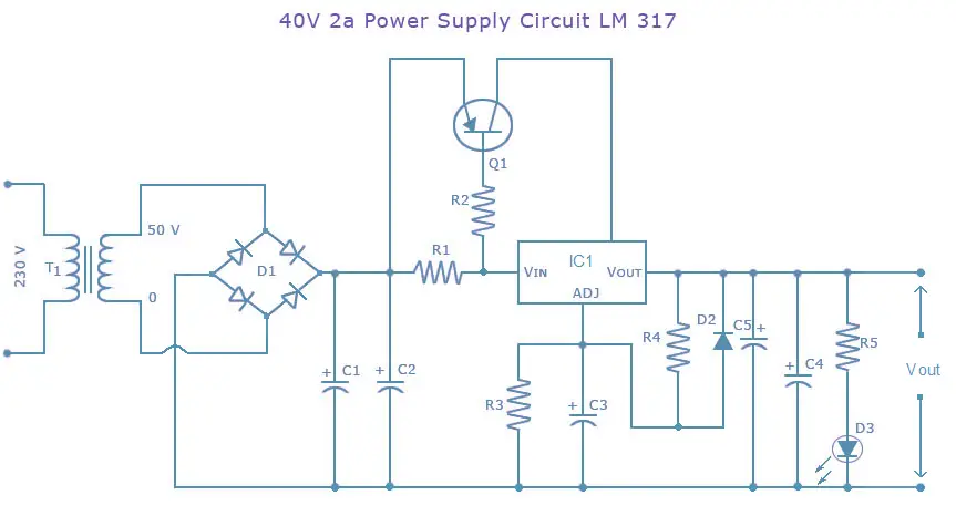
Power Supply Circuit-40 Volts-2A
LM317 is a widely used linear voltage regulator. It has 3 pins; input, output and adjustment. LM317 are energy wasters and always require a heat sink to keep the temperature of the circuit low. But due to its simplicity LM317 find a place in a wide range of power supply units.
This project aims at making a power supply circuit using the above-mentioned voltage regulator.
Description
This is a power supply circuit diagram of 40Volts, that is able to deliver 2A current. This circuit is suitable for power amplifiers. Transistor TIP 42 A is used as a pass transistor to increase the current capabilities. Voltage regulator LM 317 is the heart of this circuit. Here the out put voltage is set to 40 V by R5 & R8. If you want any other out put voltage use a 10 K pot instead of R5 and adjust it.
Parts List
R1_______________3R9 1 or 2W Resistor
R2______________ 22R 1/4W Resistor
R3_______________6K8 1/4W Resistor
R4_____________ 220R 1/4W Resistor
R5_______________4K7 1/2W Resistor
C1____________ 3300µF 50V Electrolytic Capacitor (or 4700µF 50V)
C2,C5__________ 100nF 63V Polyester Capacitors
C3______________ 10µF 63V Electrolytic Capacitor
C4_____________ 220µF 50V Electrolytic Capacitor
D1_____ Diode bridge 4A
D2___________ 1N4002 Diode
D3______________ LED Any color
U1___________ LM317
Q1____________ TIP42A Transistor
T1_____________ 230V Primary, 40V 2A ,Secondary,
Mains transformer.
Note.
If diode bridge is not available, make one using four 1N 4007 Diodes.


22 Comments
The LM317 is specified “Maximum input voltage 40 volts”
The 50 volt ac input will produce 75 volts input when no load, not clever.
Hi Leon TIP42 can handle a maximum of 4amps hence you may have to use 10nos in parallel
Hi Sir i am working on a project that requires 36 volts and 30 to 35 amp. Can the tip43 be used in parrallel the same as 2n2955 to boostcurrent output. I have Tip42 on hand.
Thanks in advanance Leon
hi frank go through the following data sheet.
http://www.national.com/ds/LM/LM117.pdf
Thanks you very much.
May I know why we need D2 to protect LM317 against C3?
Why do we need both C1 and C2 and not just use 1 capacitor instead? (same for C4 and C5)
Hi, may I know how the transistor Q1 affects the circuit? And what is the diode D2 for?
Thanks.
Frank
Q1 is a pass transistor which conducts the extra current. LM317 can handle only 1A. Diode D2 is a protection diode. Protection diodes are required for LM317 for output voltages above 25V and capacitance values above 10uF. Here D2 protects LM317 against C3.
Dear Seetharaman,
Thank you very much for the information,
More power to you.
Hi Edgardo,
you are correct. there is a mistake in the writeup.
R5 is the current limitting resistance for the LED.
output can be varied with R3(10K pot).
Here the out put voltage is set to 40 V by R5 & R8.If you want any other out put voltage use a 10 K pot instead of R5 and adjust it.
Dear Admin,
On the above quote, I am confused, I can not find R8, and R5 is a series resistor for LED (D3).
Can you make clarification on this circuit?, I would like to build one for this.
Thanks in advance.
studentproject