Description.
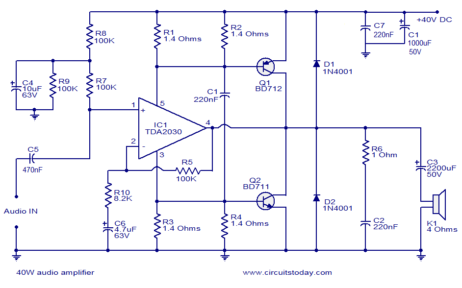
This is a very excellent 40W power amplifier design using TDA2030 IC and two transistors. The circuit employs only few components and does not require a dual power supply. The input signal is coupled to the non inverting input of TDA2030 through the DC decoupling capacitor C5. The TDA 2030 performs the major part of voltage amplification. As the IC performs amplification, the power supply current to the IC varies according to the input signal. The variations in the positive supply pin are coupled to the base of Q1 and variations in the negative supply pin are coupled to the base of Q2.The major part of current amplification is done by these two complementary transistors.
Circuit Diagram.
Notes.
- The circuit must be assembled on good quality PCB.
- The PCB tracks through which there is high current flow should be made broader.
- 12V to 40V can be used for powering the circuit. For maximum output, use 40V supply and 4 Ohms speaker.
- Transistors and IC must be heatsinked.
- Input and output grounds must be properly decoupled for optimum performance.


6 Comments
Hi,
Can I use it as a Subwoofer Amplifier with low pass filter?
Hi, if i were to want to install a voice chip, where would i have to connect it?
thank you!
Hi,
Im planning to use this amp for a 9 inch 25W sub (no big deal).
But I just want to know what the minimum current for the power supply, should be? Is 2A enough?
how about a 40 watt audio amplifier with active controls like volume control, bass control and treble control…
can you please help find this circuit….
I have send u the link go to it & enjoy the ckt … but it is of 30watt cd player ckt..
thanks 4 d circit………………………..