Description.
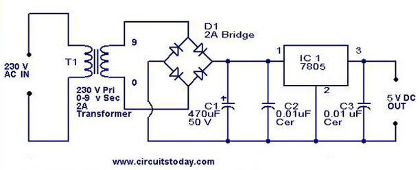
7805 is a 5V fixed three terminal positive voltage regulator IC. The IC has features such as safe operating area protection, thermal shut down, internal current limiting which makes the IC very rugged. Output currents up to 1A can be drawn from the IC provided that there is a proper heat sink. A 9V transformer steps down the main voltage, 1A bridge rectifies it and capacitor C1 filters it and 7805 regulates it to produce a steady 5Volt DC. The circuit schematic is given below.
Circuit diagram with Parts list.
Notes.
- The bridge D1 can be also made by yourself by using four 1N 4007 diodes.
- If more than 400mA current is supposed to be taken from the circuit, fit a heat sink to the 7805 IC.
23 Comments
what is the use of capacitors other than c1?
how to make a power suply with .. an output of 4.2v and 500 ma . will you please mail me??
What are the components that I will need? Thanks.
WHAT IF MY STEP DOWN VOLTAGE FROM THE TRANSFORMER IS ONLY 5 Vac? Will it cause discrepancies if I needed an output DC voltage of 5 Vdc? Thanks.
how to design dc power supply with fixed 9V output using bridge rectifier and what is the type of component use?please help me its urgent!
the transformer given with 12V
There is no need of such bulky filter capacitor. Ripple rejection of 7805 is 73dB which will take care.
can we use 4001 diodes instead of 4007
sorry its 4004 instead of 4007 & what about 470uf cap of 25v instead of 50v. i have a transformer tat outputs 9vac but i dont know about the current rating of it.
Sir is there any way to replace trANSFORMER
H Jha for low current application you can use capacitor in place of transformer like LED lights etc. but for higher current application it cannot be avoided(though theoretically possible practically not).
i have a problem for this kind of design. my transformer is heating up fast. can anybody help me? thank you and god bless.
check your transformer’s input wires if one of the two has less wire core then that’s the reson to heat your transformer
Pls,why do u have to use a 0.01uf filter at the input and output of the ic?cant that 47uf do d filtering?
Hi Rabo electrolytic capacitors are wound capacitors hence they have a series inductance component included into their circuit(refer to equivallent circuits of capacitors). hence at higher frequencies they cannot be a decoupling or coupling capacitors hence you have to add a 0.1uF ceramic disc capacitors to take care. This is more important in high speed digital circuits.
Hi Rabo As the wound capacitors contain inductive component, for low frequency they may decouple effectively but as the frequency increases decoupling will become ineffective due to the inductance of the capator is present to take care a non inductive 0.1uF ceramic disc capacitors are added in parallel with the electrolytic capacitors. please go through the following article.
http://www.usna.edu/EE/ee320/Supplements/dcdc2_capacitors.pdf
pls send me specifications and parametrs required for design of power supply using ic 7805 with fixed voltage +5v and giving current range 0-5a
Hi Kalyani you use the technique used in our earlier circuit for 12 volts.
https://www.circuitstoday.com/12v-15a-voltage-regulator
wonder site i get satisfied.i love this site.
Hi Kumardeep For a full wave rectifier you require at least 2200uF per Amp of load and will be the best for least ripple at higher load currents. In this circuit you may have to use minimum 4700uF 16volt
thank uuuuuuuuuuu
hey,will the capacitor C1 with ratings 1000uf/16V do or not???
thank you for power coircuit .it helepd me a lot