Seven Segment Counter Display Circuit
Description
Here is the circuit diagram of a seven segment counter based on the counter IC CD 4033. This circuit can be used in conjunction with various circuits where a counter to display the progress adds some more attraction.
In this circuit a 7-segment display is connected with two NE555 IC’s and CD4033 IC to display counts from 0 to 9. The IC CD40333 is a 5 stage Johnson decade counter with decoder and is mostly used in digital displays. The decoder helps in converting the Johnson codeto a 7 segment decoded output. Thus, the input signal will be converted to numeric digits and will be displayed on the LT543 display. This IC can be used in display circuits and also in clocks, timers and so on.
You may also like: Wireless Mains Voltage Tester Using IC CD4033
This IC can be operated at a maximum of 20 Volts. While using the IC make sure that you use it alternatively, as it is highly sensitive to static change, and a small touch at the input terminal would be more than enough to start the counter circuit.
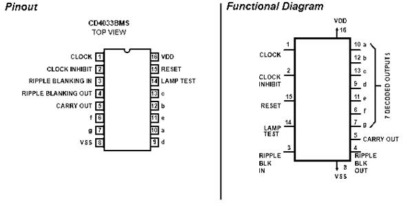
IC CD4033 Pinout Diagram
IC NE 555 is wired as an astable multivibrator for triggering the CD4033 IC on Clock Input Pin (Pin 1). For each pulse the out put of CD 4033 advances by one count. The output of CD 4033 is displayed by the seven segment LED display LT543.
Pins 2, 3, 8 & 14 are grounded. Pin 2 is the Clock Inhibit pin and should be grounded while the counter is incremented by one value for each pulse. Pins 3 & 4 are the ripple blanking input & output pins. They are used to improve the readability of the digits. Pin 8 is the GND pin. Pin 14 is the Lamp Test pin and is used to check if all the seven segments are properly working.
Pin 16 is the Power pin and should be connected to the 5V DC supply.
Pin 5 is the Carry Out pin and as the name says it carries out a 10 clock input cycle (0 to 9). It can be used to cascade more IC’s to display more digits.
Pin 6, 7, 9, 10, 11, 12 & 13 – These 7 pins are the 7 decoded outputs from a to g and produces the output digits (0 to 9) on the display.
Pin 15 is the Reset pin and must be kept LOW to reset the counter from 9 to 0.
Switch S1 is used to initiate the counting. As soon as the switch S1 is pressed, the clock input pin receives the pulse and increments the counter by 1. After counting till 9 the display again shows 0.
Diode D1 prevents the risk of accidental polarity reversal.
Seven Segment Circuit Diagram with Parts List
| Component | Specification |
|---|---|
| IC1 | NE555 |
| IC2 | CD4033 |
| R1, R3 | 47K |
| R4 | 470 Ohms` |
| C1 | 0.01uF |
| D1 | IN4007 |
| S1 | Switch |
| 7-Segment Display | LT543 |

Displaying 2 Digits (10 to 99)
Using 2 CD4033 IC’s can help you count 2 digit numbers from 10 to 99. The two IC’s have to be cascaded with PIN5 connected to carry out the count from 9 to 10 in the second IC. Make sure to connect PIN 15 (Reset) of both IC’s together & ground it with a 47K resistor. You can add more digits by cascading more IC’s.
Some circuits that you may like to see.

1. Static 0 to 9 Display

2. Up/Down Counter Circuit

3. Digital Timer Circuit

4. Long Duration Timer Circuit

5. Scoring Game Circuit
60 Comments
Also one 470k rest should be connected between 6 and 7 of ic 555
Circuit diagram is wrong……… CD4033 pin no 3 should be connected with Vcc, not ground.Pin no 5 of NE555 should be connected with ground via 0.01uf capacitor……. I have made the circuit and its working fine
can u please share ur circuit diagram..?
I makes circuit seven segment cathod ray display using ic cd 4033 it is two digit counter with ldr it counts but problem is when I reset second ic display shows 1 no in first display show during triggering. wat the problem?
can u please give me the introduction and literature survey of visitor counter using IR sensor and 2 seven segment .
Sir,
Here 555 ic is wired as monostable mode.
And you have written it in astable mode.
Please make sure. And also if it is in astable mode then what will be the value of resistor between pin 6 and 7.
Does anyone know how I can make a circuit that as an object passes between a beam of light the display goes down by one and when I press a button the display resets to 9. I have in idea for how I can use his but don’t have a clue how to make it, any help would be great, thanks.
can i use 4511 instead of 4033
when i connect battery,the display blinks n turn off,can anyone give me the solution please?
To correct this fault, connect pin no. 15 of 4033 to the ground, because it is reset pin and if we leave it open then it behaves in the same manner as you mentioned.
With this pin you can do one more thing, you can connect 220 Kohm resistor between pin 15 and Ground(0V). Now if you apply high voltage (5V) to the pin 15 then your display will reset.
when I connect battery the display blinks and turns off, can anybody help me..
when I connect the display blinks and turns off, can anybody help me..
Requirement;-To read & monitor my Battery voltage which starts from-0 to 24vDC. It should indicate or display on Red color LED display to having in built in circuit which i will be using in my units on front side.My I/P will be either 12 or 24 volts D.C.to this unit. 25pcs/month on regular (red color) & the same in green color.Type -Panel mount. Pl contact me on above mail id for more details.
Regards.
I find a circuit of 4 digit display,i welcome any one who know it to help me
wow!
thanks for your help
such a great project to make!!!!!
what changes need to be made if inplace of CD4033 , HCF4033 is used.
What are the alternatives for cd4033 in this circuit, plz reply.
is it works very good in terms of counting? is sensor present in your project?
no problem…got the solution!! 🙂
Hello..i have modified this circuit a little bit by combining the digital dice circuit and this one..i have used ne 555 timer as the multivibrator, cd 4017 as the decade counter, cd 4033 as counter and LT 543 as d seven segment..i hav used 6 leds…the problem is dat wen I press d push button..the following happens..wen the 1st LED is ON..it displays ‘0’ in d seven segment..wen the 2nd LED is ON..it displays ‘1’ in d seven segment..wen the 3rd LED is ON..it displays ‘2’ in d seven segment..and so on..plz help..i am still in the 12th std. and wud appreciate any help..it wud be also gr8 if sumone cud tell me d diff between cd 4017 and cd 4033..
HI Surya,
pin out Diagram is illustrated below
LT543 is a common cathode display.
So dont forget to ground its 3rd pin
Pinout of 7 segment display
a-7
b-6
c-4
d-2
e-1
f-9
g-10
5-dot (no need here)
Yes, You can increase the number of 7 segment display(bits) by cascading cd4033 ic…. You will get an idea about it from here
mycircuits9.blogspot.com/2012/03/wireless-mains-voltage-counter.html
can someone suggest the idea i.e on my college told to implement it using four 7 seg display
Can any body to illustrate pin diagram in refrence to abcdef and 123 of LT543 ,7 segment display LED
Thanks
D.P.Surya
hi,can i use this to integrate with motion sensor hobby kits and i want to count every person that enter count?please rply asap
Can someone please give me a circuit diagram that uses 74LS47 and 74LS90 instead of CD4033.. Thanks in advance. Please reply as soon as possible. I’ve been trying to search for it but can’t seem to find it.
I Built the TTL( 555/7447/7490 Version) in College,,, I like The CMOS Version Better!!! Thanks So Much.
Hi Daine you can use the following circuit appeared earlier in our columns. use less number of counter ICs as per your requirement
https://www.circuitstoday.com/up-down-counter-circuit
hello, my name is Daine. I’m wondering whether it is possible to make the circuit count backwards say from 9 down to 0?
cheers
I am looking for a circuit that has three 7 segment LED displays, with a potentiometer. The circuit must make the 7 segment display to show “000″ when the potentiometer is at lowest value and “200″ at maximum value. I would also like it to be remote control witha range of about 20 meters. Any information would be great.
Thanks for any help I get.
Terminals are not marked on the IC. how do I find no.1 and so on?
One pin 1 location can be located by looking for a notch at one end of the chip. Turn the chip so that the notch on the chip is facing left. Now look at the lower left side of the chip, that will be #1 pin and the numbers will be sequential from that point to the end of the pins in that row. Another identification of pin #1 is to see a dot at one end of the chip. Turn the chip as in the instruction above and see pin one in the same place, (lower left side) pin #1.
hey frnds,i want to make a project using cd4033,555timer,7segment display and want’s to give trigger to 555 by LDR and LED as when beam will cut ,555 should trigger and give a count..plz can anybudy help me out hw to implement this…………..???????????/i need it in 2days plzzzz….thanksss………
Hi Zakaria use set / reset flip flop before the counter it will take care. first touch it will get set second touch it will get reset third touch it will get set etc.
plz give the layout of seven segment counter its very important for me so plz help
dear recently we have designed a seven segment visitor counter just by using simple components rather than micro-controler. if u want the circuit diagram so e-mail me at (engr.ferozkhan@yahoo.com)
hi.
i am sumon.i study diploma in electronics.i follow this ckt & i satisfied
I need an electronic circuit to display the two-digit seven-segment display, which displays the numbers 01 to 99 on every odd count touch (1, 3, 5 and so on), using a touch switch plate. As detailed steps:
– touched the first time, displaying the numbers 1;
– touched the third time, displaying the number 2;
– touched the fifth time, featuring the number 3;
– touched the seventh time, showing the number 4. And so on.
Can anyone help? Thanks!
Hi, just a small enquiry.
I am using the PIC18f4520.
How do i count my dual seven segment from 0 -60 and stop?
I would like to know the coding for this function.
Yr help would be much appreciated.
Hi Urvish the following site out line B is your requirement
http://www.datasheetcatalog.org/datasheet/hp/HDSP-5507.pdf
Hi Urvish the following sites will give the required data
http://www.datasheetcatalog.org/datasheets/134/108993_DS.pdf
http://www.datasheetarchive.com/LT543-datasheet.html
HEY CAN ANYONE HELP TO GET THE DATASHEETS OF IC–CD4033 & 7 SEGMENT DISPLAY–LT543 ???
I NEED IT IN COMING TWO DAYS .. PLZ HELP…
i am looking for a circuit that has two 7 segment LED displays, with a 555 timer,ic 4033,12v dc supply and a light sensor. Kindly help me in this regard.
Regards,
sweta
i ws lukng for layout of 7-segment BCD counter…
pls help me!!
Hi Kumar it is just a up counter from 0 to 9 and restart again that is all. Pl refer data sheet
http://www.datasheetcatalog.org/datasheets/134/108993_DS.pdf
I do not find the up counter, with clock and reset as the input port and Cnt and Hit as the output port in pspice-capture CIS. Please help me.
thanks thanks
Yes Ravichandran it has got market potential in India as most of our indoor games require it, provided you can match the brass variety or may be little costlier. you may have to produce in very large quantity to maitain low price. better to ofload your idea to some taiwaneese co and get the chip and display from them. you cant just match their price and quality.
hi
i want to know about the market potential & competitives of dice with 7- segment display counter.
Iam a new student in Electrical & Electronic engineering
Thanks a lot yaar ………………….
i want to know about the seven seg ment with two ic 4033 of mod 99 counter
i am looking for a segment display using a florescent Lamp, how cOuld i dO that one??
would sOmeone help me plzz..
iam looking for an led display ciucuit diagram of 10 segement control by a switch
i am clement looking for 10 segement led display circit diagram that can display number control by a switch
This is a very good up/down counter circuit
https://www.circuitstoday.com/up-down-counter-circuit
i want to know about the market potential & competitives of dice with 7- segment display counter
circuit for two 7 segment displays, where they
add up giving approx 30 on the display must also beable to be reset. there must be 3 press to make contact the first must add 1 to the display second must add 2 to the display and third must add 3 to the display. hope you can help
thanks peter
hi
i am chitresh & i am looking for the working detail of CD4033 (counter,seven segment display driver ),CD4071 OR gate for my project.Actually, Iam a new student in Electrical & Electronic engineering.
Would any body help me please?!!
Hello,
My name is Redha and iam looking for counter circuit with two 7segment LED using the pic for my project.And I will use two photocell sensors to count up and down.
Actually, Iam a new student in Electrical & Electronic engineering.
Would any body help me please?!!
mixalmix2001@hotmail.com
I am looking for a circuit that has two or three 7 segment LED displays, with a potentiometer of 1M or 10 M.The circuit must make the 7 segment display to show “000” when the potentiometer is at leaset value and “100” at maximum value. Kindly help me in this regard.
Regards,
Prabhu