Description.
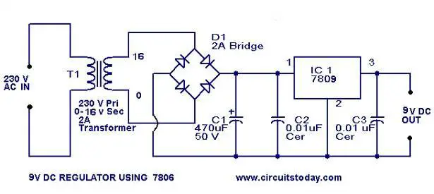
Here is the circuit diagram of 9 V regulator using popular 7809 IC. The 7809 is a 9 Volt voltage regulator IC with features such as internal current limit, safe area protection, thermal protection etc. A 16 V transformer brings down the 230V mains, 1A bridge rectifier rectifies it and capacitor C1 filters it and 7809 regulates it to produce a steady9V DCÂ output.
Circuit diagram with Parts list.Â
Notes.Â
- If a current of 300 mA or above is required, fit a proper heat sink to the IC 7809.
- If 1A bridge is not available, make one using four 1N 4007 diodes.
Thanx sir…I love dis
is it ok if i use 220v primary&15v secondary?while the others still the same?and what puse should i use?
Yes Morr you can use 15 volt secondary transformer.
thanks again man.. 🙂
thanks man!
where can i put the LED ???
In the output 9 Volt by using LED and 330ohms 1/4 watt in series with it.
C1 and C2 has blown because you might have used 16 or 25 volt capacitors use 50 volt rated capacitors only
thanks for the info man.!
When i try it on MultiSim C1 and C2 exploded. i don`t know what`s wrong.
sir I tried. to power a tone control. circuit of 12v from 35v using a 12v regulator (7812).I used a heating, so after working for about 3minutes d regulator got bunt. sir wat could be d possible reason for dat?
Have you used a good heat sink. what is your tone control current requirement. 35-12=23 volt drop hence you can draw to a maximum of 40mA with a good heat sink. if input voltage exceeds 37 volts also the ic will get burnt without drawing any current. please check. if voltage is >37 use a dropping resistance of suitable value to reduce input to 24 volts.
can this circuit output power up arduino?
Yes. With all I/O port loaded the current requirement of Arduino is < 500mA.
Do I need a heatsink for the 7809 under 1A transformer? tnx
Please go though notes it clearly indicates above 300mA you require proper heat sink.
Can the regulator be changed into a 12v regulator without any other change in the circuit?
The regulator can be changed for 12 volt and also for 15 volt, which is maximum for the specified transformer.
Sir,
is there any way to replace transformer
Theoretically yes. practically not useful. for low current application with capacitor you can replace transformer not for high current requirements.
sir i want full theory about power supply and also want to know how 1 can calculate which diodes / transisters one can use for the specific value of power supply? How this calculation is done?
give me a link at my email id for automatic street light using scr and relay…
sir pls send the all notes of this project to my mail bcoz my submission on monday.
so i need it. pls pls sir…
thanx in advance
it’s vital for this project not need ianother notes. its sufficient
Are you sure about diodes in rectifier. They are upside down.Where is + must be ” – “.
is there a 230/220vAC to 12vDC transformer that is small in size? can it work with this circuit? and is this circuit capable to hold five loads for example different effects for guitar, if not how many can it handle? Thanks…
yes chethan its better to use 12v and 12v is easy available in markt, so go with that
Hi Chetan with 9 volt transformer the DC at the input of IC will be 12 approx. will not be sufficient. Minimum should be greater than 10.5 volt, hence use a standard heavy duty 12 volt transformer.
Sir i whant make a street light circuit project for my polytechnic diplom i am electrical engineering student so plz give me some idia sir i m wating for your answer…..
Sir, can I use 9 volt transformer.
sir, will this ckt work with sunlight or only in the night time?.. if it works based on sunlight during monsoon there will be no sun.. then the light will glow continuosly during day time also… is this not a disadvantage? and ALSO please SEND ME THE COMPLETE REPORT THIS TOPIC to my mail.
hi sir i want full theory of working of this to my mail
eeesparksvag@gmail.com
am not geeting relay response with change in light
iam getting output less than 9 volts nearly 8.7
sir iing out put made total ckt bt am not geting output sir
Hi Harish grounding for electrical system at home or for any electronic gadget
how to provide grounding sir please reply me
thank you
Hi Harish you can use.
Hi Caloy it is not possible
Hi Larry you have to use 6 1N4007 diodes in series in forward biased condition between regulator common and negative bus to achieve 9volts from 5 volt regulator
sir can we use 230/12 v transfomer instead of 230/16 v please give reply to my mail its too urgent
good day sir,,
how can i divide the 1 amp output into three isolated 300mA output…???
DEAR sir i wish to do some change to ur circuit for to make lights for home it’s very nice…..
I have also made power supplies using this method, virtually identical to your schematic, with one difference.
I did not have a 7809 regulator, but I have hundreds of 7805’s left from my old company. I needed the power supply right away, and there is no local source for the 7809.
I solved this problem by using the 7805 in place of the 7809, but, I placed several rectifier diodes (of the 1N400X family, but others will work as well) in series with the 7805 GND (pin 2 in your schematic) pin, that is, between pin 2 and the negative side of the power supply. The diodes are connected cathode to anode, so they will conduct when properly biased by a DC voltage/current, and the anode of the first diode in the series string is connected to pin 2 of the 7805. I believe I used 3 diodes, as the series combination had a voltage drop of about 4 volts, though it isn’t important to use 3; all that matters is that the series forward voltage drop is, in this case, 4 volts (I measured the forward voltage drop of each diode, selecting from a larger quantity of diodes, ones that fit my need, that is, those that yielded a total forward voltage drop of four volts). I also connected a 3K resistor from pin 3 of the 7805 to pin 2, to provide bias current for the series diodes, but the resistor value is not critical, as long as a few mA of current flows through the diodes independent of current from pin 2 of the 7805. A 4 volt zener diode would work here also, in place of the rectifier diodes, but they are not often stocked by experimenters!
Sometimes, it is a good idea to add a capacitor from pin 2 to the negative supply, to bypass the diodes, and give good transient response, since that pin is now “floating” above the negative supply and may cause some problems if the power supply needs to furnish power to a load which produces fast transients which the supply needs to control. The capacitor value is not critical; I over-killed it with a 10uF electrolytic and a 0.1uF ceramic in parallel. Since it was only a one-off power supply for bench-top use, I didn’t worry about costs; I just used what I had on hand.
This can also be accomplished by using a voltage divider with two resistors. One is connected in series with pin 2 and the negative supply (be sure to remove the connection from pin 2 to the negative supply which is shown in the schematic), while the other is connected from pin 3 to pin 2. If you make the first resistor variable, you can make the power supply variable from 5 volts to about 12 volts or so, depending on the transformer and rectifier voltages and current rating. Also, it is a good idea to heat sink the 7805, as it will heat up quickly if more than a few mA is drawn from the supply.
These instructions are sketchy, I know, but perhaps someone will place more information here to show how it is done, as I don’t have anything which allows me to put a schematic here.
Hope this is of use to someone.
Larry (I apologize if there are any errors; if I can help, contact me at lspeed1 at comcast dot net.
Maybe We Should Increase C1 to 1000-2200 uF To Improve Filtering Action and Reduce Ripple. A LED in series with a 470 ohm Resistor would be Nice At the 7809’s Output. Otherwise a Great Power Supply To have on your Bench!! Nice Circuit Too!!
Really luv dis, and it helped me alot on my project wrk, which Design and construction of Automatic street light control switch thanks………..
can i use 230:12 ,2A transformer instead of 230:9 ?and components will remain same?
Hi JHKNJ you can use center tapped transformer of minimum 12 0 12 or greater may be upto 18 0 18 with a good heat sink for the regulator IC, if you are likely draw higher current.
Thats a gud 1. can u pls tel whether a full wave rectifier can b used instead of bridge and a center tapped transformer in the place of 230v,13v transformer
That thing looks very nasty and slimy too.
thank you to this circuit we actually made like this for our project and it works. we also add some features like fan, LED with resistor connected is series for much beautiful outcome. we use a transformer which is 220V, 12V @ 1A. thank you…
Ðа тебе боже что мне не гоже гыгыгы 🙂
very good 9 V voltage regulator circuit
this regulator,is can to charger a lead acid battery because my battery work it less than 7,5-8,0v.
hi there
i can’t understand what you have written, pls write clearly