Description.
Here’s a low cost radio circuit that can be used to listen to the radio conversations between aircrafts. The radio circuit based on transistor 2N918 and diode 1N82 receives in the 220Mhz to 400Mhz range. Capacitor C1 and inductor L1 forms the tank circuit for tuning. Diode D1 performs the detection. Transistor T1 performs the necessary amplification. The out put audio signal is just enough to drive a small headphone. For driving speakers.
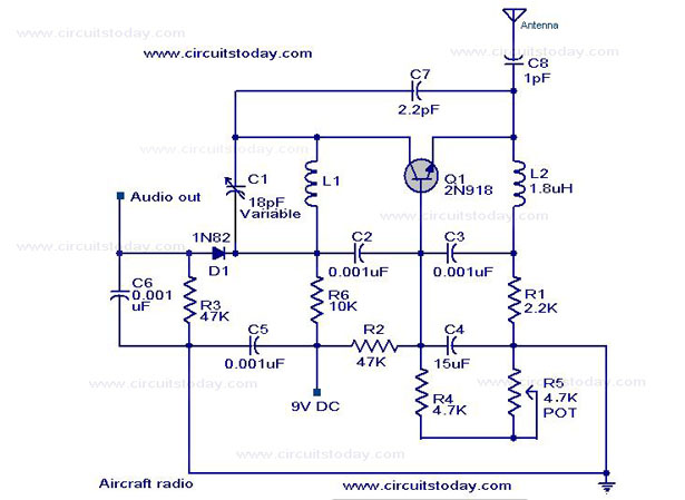
Circuit diagram with Parts list.
Notes.
- Use a 45cm long wire for antenna,
- For L1 make 2 turns of 22 AWG magnetic wire on a 5/32 steel bolt.
- POT R5 can be used for adjusting the sensitivity.
- Assemble the circuit on a good quality PCB.That’s an important factor.
11 Comments
ok nevermind i figured it out: P(w)=V(v) x V(v)/R(ohm) =
R1=0,0368181watt
R2R3=0,0017234watt
R4R5=0,017234watt
And Check – V(v)= √”””””””””” P(w) x R(Ohm)
ok so i have a problem:After some calculation… R1-1amp/R2,R3-2amp/R4,R5-1amp.//And the wattage : R1-1watt/R2,R3-18watt/R4,R5-1watt. So my questio is how is this possible for
R2, R3 – 18 watts. and 47k ohm???
V(v)=P(w)/I(A) // V=18/2=9 Volt battery.
The mathematics is correct so is it circuit wrong or am i not smart enough?
I think aircraft band is about 110~180 MHz range..
What do you mean about good quality PCB. Do you mean to just be sure of the quality of soldering.
What are equivalent diodes and transistors as the ones mentioned are hard to find. An RF buffer should be used. Try Sanyo parts “but doubtful they will work”?
DOES THIS CIRCUIT WORK AT ALL!
An RF buffer stage such as the one here:
http://krysatec.benghi.org/phprs/images/200603311425_Superbuf.jpg
Will help improve the performance of this receiver. Please see the notes in the link. Also note, you should use a 2N918 or eqiv. transistor. A 2N3904 will not operate at 220MHz to 400MHz.
Hi Enginar 1N82 is a General Purpose UHF-MW Mixer Diode
with a Noise Figure Max. (dB)=16 and in Package=DO-7.
you can try Sanyo 1SS345. Any point contact diode can be tried. you can try 1N4148 or 1N914 but i am doubtful about its suitability here.
Hi Waqas you can use your cable tv input and try to receive audio of TV Band-III or cable channel S Band.
Hello,how can we test this circiut if we have not any aircraft near to us
1N4148’i deneyebilirsin!
Hello, I’m having trouble finding the 1n82 Diode. Are there any alternatives?
Thanks