Automatic Railway Gate Control System Using Arduino & IR Sensor
About a million people have died over the past 5 years in unmanned railway crossings all over the world. At least 1/3rd of the railway crossings are unmanned due to their remote placement and less traffic. The Automatic Railway Gate Control System using IR Sensor & Arduino focuses on systematic traffic control of railway gates that are both manned and unmanned. This project will not only make the system more reliable & precise, but also save the authorities from hiring man power to do the job. You may take it as a onetime investment.
The Automatic Railway Gate Control System Project makes use of an Arduino Nano to control the whole circuit. Two Servo motors are used to open and close the railway gates. Four IR sensors are used for sensing the arrival or departure of train. The main objective is to close the railway gates when the train approaches it, so as to block vehicles from going across the track. As soon as the train moves further away from the railway crossing, the gates must automatically open to allow vehicles to cross by.
Components Used
| Components | Specification | Quantity |
|---|---|---|
| Arduino | Nano | 1 |
| Servo Motor | G9 | `2 |
| Buzzer | 1 | |
| IR LED | 4 | |
| Photodiode | 4 | |
| LM358 | 2 | |
| Preset | 10K | 4 |
| Adapter | 12V | 1 |
| LED | Red | 4 |
| Resistors | 10K | 4 |
| Resistors | 330 Ohms | 8 |
| Toy Train | 1 |
Automatic Railway Gate Control System Using Microcontroller – Circuit
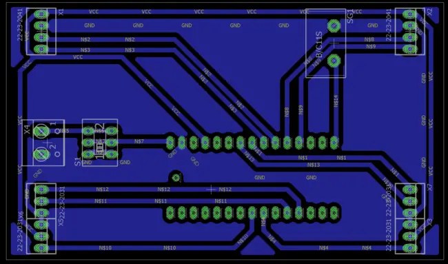
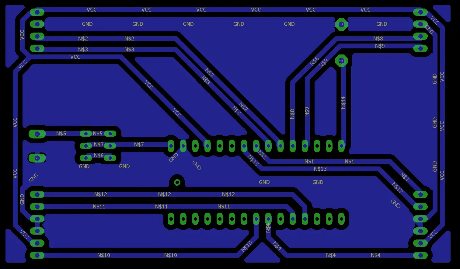
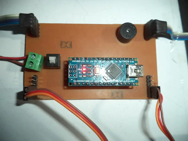
The automatic railway gate control makes use of 3 PCB’s. One is for the Arduino Nano, which works as controller of the whole project. The other two PCB’s are needed for the IR pairs. I designed all the three PCBs on EAGLE CAD software. If you want to make etched PCB, refer both the figures given below.
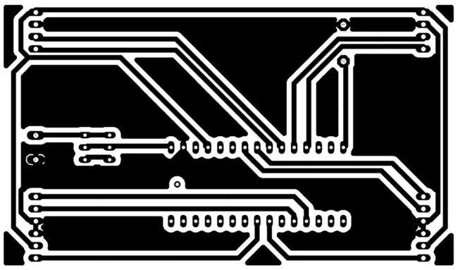
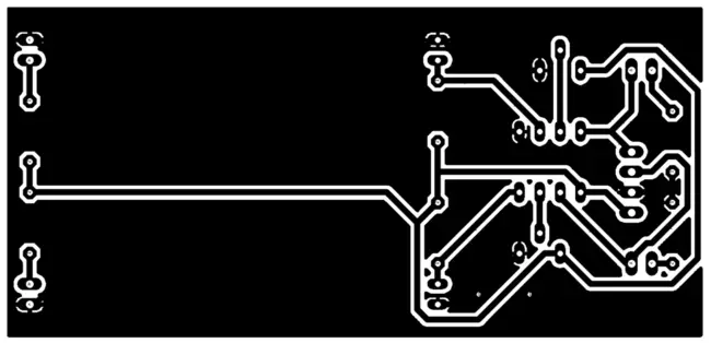
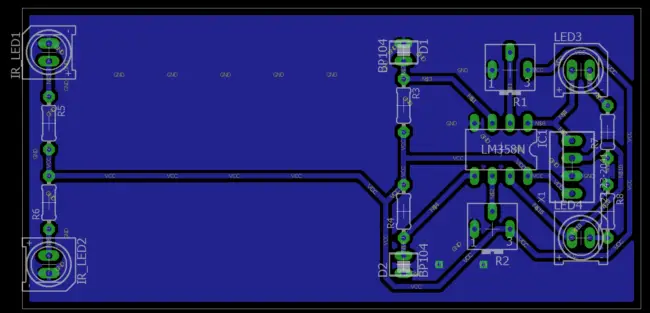
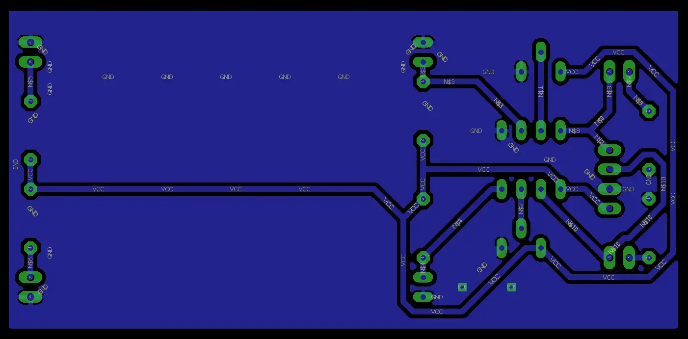
If you want to make the circuit on zero PCB or breadboard refer both the figures given below.
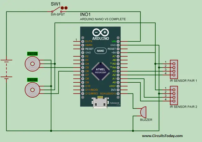
Output of all the sensors are connected to A0, A1, A2 and A3 pins of Arduino.
The pins D9 and D10 of the Arduino are PWM pins. These pins are connected to the Servo motor. Servos are controlled by sending an electrical pulse of variable width, or pulse width modulation (PWM), through the control wire.
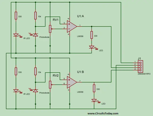
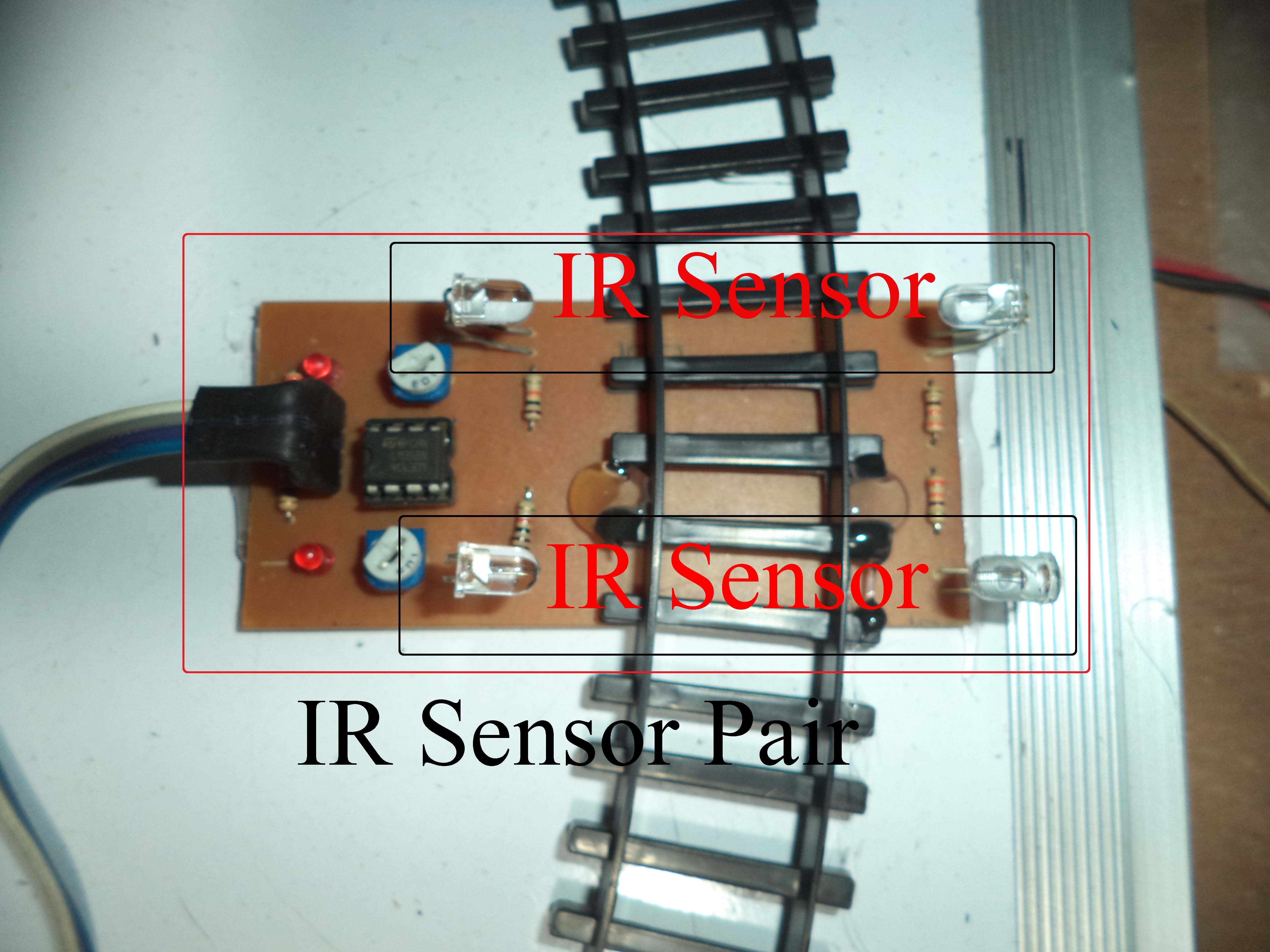
IR pair is made with dual Op-amp IC LM358. Only one IC is required for a pair. A preset is used for calibration.
IR Sensors
Two IR pairs are used in the project. If you are familiar with PCB etching you can etch the PCB, but it is not necessary to use the etched PCB, you can use two IR sensors instead of one pair that is easily available in market.
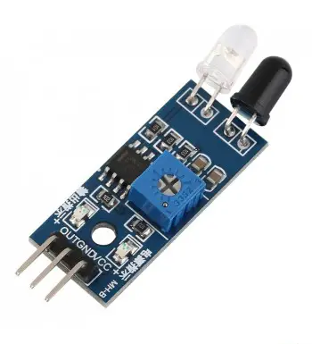
If you are using ready-made IR sensors please replace “<” into “>” and “>” into “<” in the code, because output of ready-made IR sensor is invert of the sensor pair used in the project.
Working
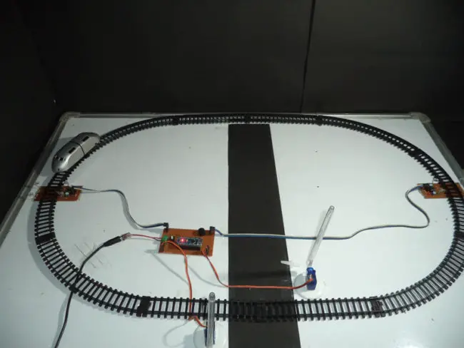
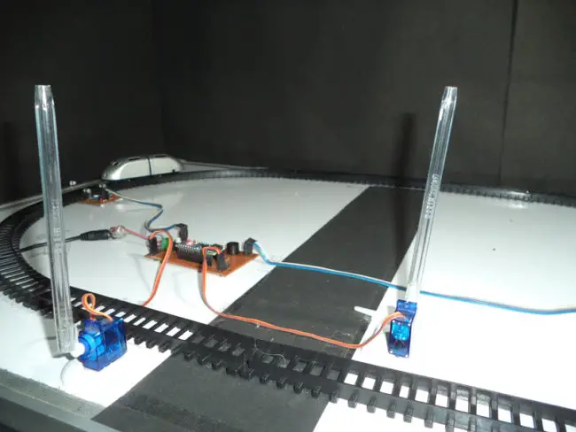
Four sensors are used in the project as two pairs of two sensors; these sensors are kept in the both side of level crossings gate as shown in Fig 1. All the sensors are connected to Arduino.
When train arrives from any side, it first cross the sensor1 after that cross the sensor2, in this way Arduino close the gate by sending the signal to servomotor. When train departure from any side it first cross the sensor2 after that cross the sensors, in this way Arduino open the gate.
Servomotors are used in the gate because it is very easy to use and does not require any driver IC or circuit. Servo motor has three pins. The first pin is PWM, second is Vcc and third is GND. Servo motor receives the PWM signal from Arduino and rotates the motor at fixed angle according to duty cycle of signal.
Calibration
There are two presets in an IR pair circuit. Before calibration make sure that IR LED and photo diodes are placed in front of each other, and falling on Photodiode
Now rotate the preset, till the indicator LED does not glow. When some barrier is placed between LED and Photo diodes, indicator LED starts glowing. This calibration procedure has to be done for all the sensors.
Video
In the video, the speed of closing & opening of gate is slow, so it would be better if you will use the slow train. For increasing, the speed of opening and closing decrease the delay in line 71, 73, 84 and 86.
Program Code
In the code two libraries “EEPROM.h” and “Servo.h” are defined. In the project, two servomotors are used so in the fourth and fifth line two servomotors are defined named myservo1 and myservo2.
Now some integers are declared, “pos” is the position integer for servo. After that, four sensors are declared named “sensor1”, “sensor2”, “sensor3” and “sensor4” are used to connect Arduino after it an integer is declared by name buzzer.
In the void setup section both the servo motors are attached by function “myservo1.attach (5)” in this function 5 is the pin number. Now all the four sensors are declared as input device by using function “pinMode(sensor1, INPUT)”. Buzzer is declared as Output device using function “pinMode(buzzer,OUTPUT)”. Now EEPROM.write(0,0) function is used to write EEPROM of Arduino.
In the void loop section if condition is used, When value in EEPROM address1 and address2 is become zero, system come in if loop. Now a while loop is used when train come and cross the senaor1 system come in this loop, after that an if is used when train cross the senaor2, EEPROM (0) and EEPROM(1) are updated by one. This same approach is used for sensor3 and sensor3.
Another “if” loop is used in line 48 and it become true when value of EEPROM(0) is Zero and EEPROM(1) is One. After it while loop is used and it become true when train cross the senaor2 and when train cross the senaor1, EEPROM(1) is updated by Zero and EEPROM (0) is updated by One. And this same approach is used for sensor4 and sensor3.
EEPROM(1) indicates the status of gate, when value of EEPROM (1) is One gate is opened and when EEPROM(1) is Zero gate is closed
Now in line 65 an if loop is used, it become true when value of EEPROM (1) is One now servo rotate from zero to 90 degree and gate opened. “digitalWrite” function is used to make buzzer On and OFF in line 70 and 72. After all EEPROM (0) is updated to zero. This same approach is used for closing the gate.
13 Comments
Can we us the IR sensor module which is available on Amazon
Sir,
Pls describe this situation also…
If anyone stuck at railway track and gate is closed.
how to create a sensor circuit. teach them
Bro y r u using 4 ir sensor v can use 2 right??
sir , should we use the PCB and then build the circuit u have given . can u please tell more clearly . it would be very helpful if u do at the earliest . thank you
I was using 12V,2A (max) adapter and ic asm1117 got burned.what should i do now?
Sir. I need your help please help me I am made this project but this is not working I am adjusted the preset but led is always glow please help me
It is awesome.
can it be programmed in nodemcu esp8266 instead of arduino ??
Is the code require any change or connection require any change when we are using nodemcu esp8266 rather than arduino?
Sir, In line 43 you are using a logical “or” operator . I am bit confused . I think it should be logical “and” . Can u please clarify my doubt.
Instead of using two arduino s can we use a time deay for the single ir sensor to open or close the gate!
You can use one sensor in place of pair but then the drawback will be that the sensor will open gate even if any human being will walk on the track . The program here is basically based on the length of the train . By using pair of sensor we can prevent the unwanted detection of human beings .
This is what I have understood and performed in my lab .
so good project.iam impressed
I want this kit .how much cost it will be