Description.
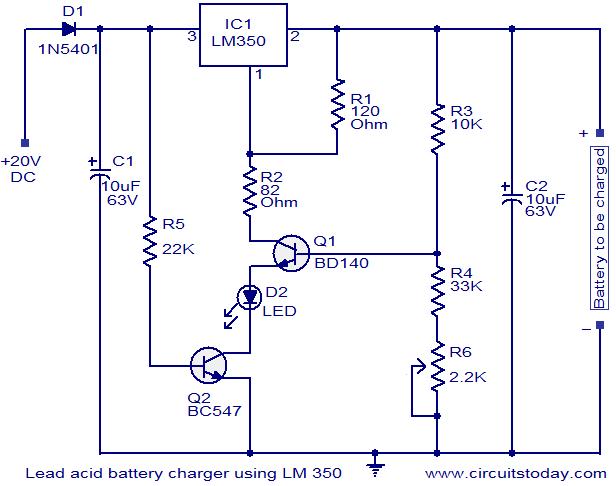
Here is a simple circuit using IC LM 350, which can be used for charging 12V lead acid batteries. This circuit is perfect for “constant charging” 12V lead acid batteries. The circuit is designed as a constant voltage source with a negative temperature coefficient. The transistor Q1 (BD 140) is used as the temperature sensor. The transistor Q2 is used to prevent the battery from discharging through R1 when the mains power is not available. The circuit is designed based on the voltage regulator IC LM350.The output voltage of the charger can be adjusted between 13-15 V by varying the POT R6.
The LM350 will try to keep the voltage drop between its input pin and the output pin at a constant value of 1.25V. So there will be a constant current flow through the resistor R1. Q1 act here as a temperature sensor with the help of components R6/R3/R4 which more or less control the base current of Q1. As the emitter/base connection of transitorQ1, just like any other semiconductor, contains a temperature coefficient of -2mV/°C, the output voltage will also show a negative temperature coefficient. That one is only a factor of 4 larger, because of the variation of the emitter/basis of Q1 multiplied by the division factor of P1/R3/R4. This results in approximately -8mV/°C. The LED will glow whenever the mains power is available.
Circuit diagram with Parts list.
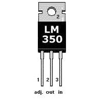
Pinout of LM350.
Notes.
The transistor Q1 must be placed as close as possible to the battery.
Use a 20 to 30 V / 3A DC power supply for powering the circuit.
This circuit is not possible for charging GEL type batteries as it draw large amounts of current.
10 Comments
Hi Johnsheen since this is a regulated power supply once the terminal voltage of the battery raises the currnt will fall down to trickling level. hence can be used with solar PV cells. But this will not work with lower intensity of light during passing cloud etc. It is always better to use a charge controller for charging from Solarcells since they have a wide voltage output depending on the illumination they get ( hence a switched converter is the best suited for PVCs)
Can I use this circuit to a solar panel to charge the car battery ? Does it have over charge protection ? If not how to modify this circuit ?
Hi Thanassis you are correct both can be BC547. but for temperature sensining Q1 can be a metal transistor.
Hello!!
Thank you for your nice site, very intresting…
…but BD140 it is a pnp transistor, and in circuit apears as npn.
Even more, as a pnp it will always allow current to led, no matter what trimmer R6.(R6 WILL BE USELESS BECAUSE Q1 WILL ACT AS A DIODE) I’m sure you could use BD135 which is a npn, as the BC547. Ferther more,almost all the current from Q1 passes throu Q2 (BC547) so i think it is an idea to use BC547 as Q1 too.
AGAIN THANKS FOR YOUR IMPRESIVE WEBSITE – KEEP UP THE GOOD WORK!!!
GREETINGS FROM GREECE!!!
Hi,
I am joynal. i have led asid battery , i wan’t to charge my batterie.
can you give me battery daygram… 12v 50A.
How can this diagram be modified for to charge a 24v 5A charging current?
thanks
Hi DYK You can increase the input 32 to 36volt DC and increase R3 to 20K and decrease R4 to 3.3K(in the original charger circuit it should have been 3.3K for correct operation) and set out put with pot R6 for 27.6 volt. Never exceed 3 amp charging current, use good heat sink for LM350.
How can this diagram be modified for to charge a 24v battery?
how a battery charger can be connected for a susstation back up power supply.
This Battery Charger using LM350 was
already published in Elektor magazine.