Car Audio Amplifier Circuit
Description.
A simple low power car stereo amplifier circuit based on TDA 2003 is shown here. The circuit uses cheap, readily available components and it is very easy to construct. TDA2003 is an integrated car radio amplifier from ST Micro electronics that has a lot of good features like short circuit protection for all pins, thermal over range low harmonic distortion, low cross over distortion etc.
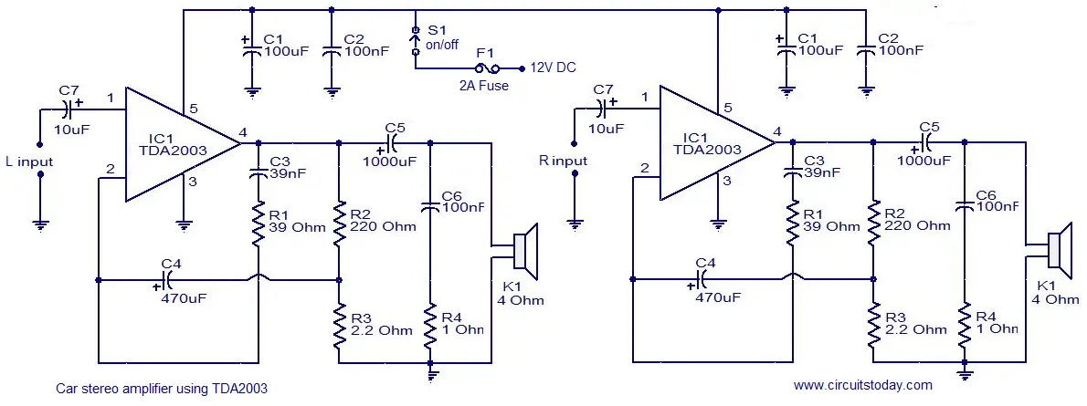
In the circuit given here each TDA2003 is wired as a mono amplifier operating from a 12V supply. Resistors R2 and R3 forms a feedback network that sets the amplifiers gain. C7 is the input DC de-coupling capacitor and C5 couples the speaker to the amplifiers output. C4 is used for improving the ripple rejection while C1 and C2 are employed for power supply filtering. C3 and R1 are used for setting the upper frequency cut-off. Network comprising of C6 and R4 is used for frequency stabilization and to prevent oscillation.
Car audio amplifier Circuit diagram.

Notes.
- Assemble the circuit on a good quality PCB.
- Heat sinks are necessary for both ICs.
- The circuit can be operated from 12V DC.
- S1 is the ON/OFF switch.
Other Audio amplifier circuits in our website,that may interest you;
1. Car Stereo Amplifier Circuit – using TDA1553
2. Audio Amplifier Circuit – using TDA2040
3. 6 Watt Hi Fi Audio Amplifier
4. Mosfet Audio Amplifier Circuit

18 Comments
Sir, can we use this circuit for a 40W 4 ohm speaker. I want to have an amp for my car which must be compatible with this speaker.
Plz, suggest me some other amp circuit in case we cant use this circuit with 40W 4ohm load.
Thanks
what is the voltage rating of the capacitor i used in this circuit?
Hi Rex it is still a 10 + 10 watts stereo amplifier. Cannot be a single 20 watt mono amplifier. If you connect them in bridged mode, theoretically you will get 4 times the power into the same load. That is one amplifier will amplify positive portion of the signal at the same time the other will be amplifying the negative portion so the excursion voltage across speaker doubles. That is the power will get by 4 times as power is Voltage square divided by the speaker impedance. But practically as per manufacturer you will get 18watts
Seetharaman, There are two audio amplifeirs here connected together, and each of them produce 10W at output,.. my question is… Can the two amplifeirs produce 20W output
There are two audio amplifeirs here connected together, and each of them produce 10W at output,.. my question is… Can the two amplifeirs produce 20W.
i wanna report for car audio amplifier..plz send me with in this sunday
Seetharaman, what class does this Amplifeir belong?
Hi Rex between class AB and B as there is a quiescent current of 50mA is consumed by output stage to overcome crossover distortion.
Seetharaman, are we connecting the two Right (R) terminals of input of the two amplifeirs together? And the two Left (L) input terminals of the amplifeirs together?
Hi Rex common goes to ground (power supply 12 volts -ve terminal) and core(center lead of input coaxial cable) goes to input coupling capacitor C1.
If you are asking for bridging, the input is directly connected to one amplifier and inverted (180deg out of phase) signal is connected to other amplifier and seaker is connected between both amplifier output terminal IC pin no4 (speaker one terminal to one IC pin4 and other speaker lead to other ic pin4)
Seetharaman, please give us the Bridge circuit of this amplifeir
Hi Rex use the following link
http://www.unisonic.com.tw/datasheet/TDA2003.pdf
How can i BRIDGE this two ICs together to get only “ONE” OUTPUT and also boost the power output of the circuit
does all your circuits are work perfectly ??
coz some websites that i had been searched about circuits are have some errors ., that is why its hard to trust now in any websites that they didin’t proven..
Hi Jithin connect all earth point together to -12volt. For clarity of circuit, without showing so many inter connections, the circuits are normally shown like this. all ground points are normally common reference point.
do i join the ten earth points together. and where do i connect the -12v dc.
C3/R1 can be left off if you don’t want the bass boost. These ICs can drive as low as 1.6 ohm spkrs. They can also use up to an 18V supply. C4 doesn’t need to be 470uF; 47uF is fine.
good diagram i like it and the funtioning to