Description.
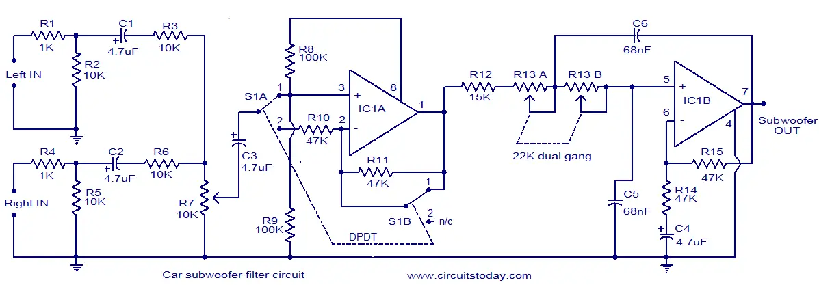
Here is the circuit diagram of a simple subwoofer filter that can be operated from a 12V DC supply. Such a circuit is very useful in automobile subwoofer applications. The circuit is nothing but a low pass filter whose pass frequency can be adjusted between 60 to 160 Hz.
The circuit is designed around the TL072 dual BIFET opamp IC. Out of the two opamps inside the chip, IC1A is wired as a buffer. The left and right audio inputs after mixing is fed to the input of the IC1A using the DPDT switch S1. Switch S1 is the phase control switch which can be used to make the subwoofer in phase with other speakers. When S1 is in position 2, 180 degree phase shift will be induced.POT R7 can be used for controlling the level. IC1B forms the low pass filter whose pass frequency can be controlled by adjusting the dual gang POT R13.
Circuit diagram .
Notes.
- Assemble the circuit on a good quality PCB.
- The circuit can be powered from 12V DC.
- IC1 must be mounted on a holder.
- S1 is a DPDT switch.
- R13 should be a dual gang linear POT.
- C5 and C6 must be polyester capacitors.
- POT R13 can be used for adjusting the pass frequency.
- POT R7 can be used for adjusting the level.


30 Comments
both ic has given 12v supply?
where to given 12v supply in this filter circuit
HI SIR,
CAN I USE TDA 2050 AMPLIFIER FOR THIS FILTER.
THANKS
If you want powerful sub-sub sound, put a linkwitz filter on the front end. This will overcome a poor performing speaker by putting a gain boost on the lower frequencies. If your speaker rolls off (for example) below 40Hz, you can make it perform down to 20 HZ if you want using the linkwitz filter.
can the inout be from any weak audio source or does it need to be pre-amplified? because it provides weak bass as compared to the other two channels. I made a 3 channel amplifier and fed output of this circuit to 3rd amp.
I used this amp circuit
https://www.circuitstoday.com/car-stereo-circuit-using-tda2040
Hello sir, i make this circuit on split supply, but i want its work with singal supply.can u email the pcb layout or any webside who has pcb layout. If u help me then my 2.1 soundsytem complete.
I like this circuit, please sent to me pcb for this project, thank you.
I can provide you its PCB as well as its tutorial videos for only 5$ ….
Hi sir this circute is to be connected before amplifire or direct subwoofer please reply me
yes this circuit is connected before the amplifier and you can use it in any amplifier to make it a subwoofer amplifier..
for more information please contact me
engr.omer9@gmail.com
can i connect it to any amplifier or there is a specific amplifier???
you can connect any amplifier with it
HI.. this can be done using a simple RC lowpass filter adding input of power amplifier ..
yes you can obtain low pass sound with RC filter but it does not give effective bass as this opamp based circuit gives…
Hello ser can you send me a pcv design for these circuit because I’m interested to make these project.
it was a ampli there?
the output of the subwoofer needs to amplifi…..
the circuit given is a filter circuit….
hi, im ashok
1,do we need to amplify the subwoofer output or we can feed it directly to it?
2,if we have to amplify it ,then wats the amplifier circuit?
3,moreover the pin 8 is supply but it is connected to 3rd pin via 100k, is that rite?
4,is the input is preamp input or amplified input?
anybody plz reply,,,,,
my email is ashokpkumar@yahoo.com
yes you need to amplify its out because this circuit is only a filter and has very few mili volts output… so it must be definitely amplified.
There is no specific circuit for this amplifier you can use it at the input of any amplifier
pls. Ineed i complete circuit on an automatic voltage stablizer
Hello, greetings from Argentina, I’m interested in making this circuit. I’m not good in the design of PCB’s, will have a chance to send me the pcb for this circuit to my mail?
Thank you!
For PCB kindly inbox me
engr.omer9@gmail.com
Hi Pin No 8 of IC TL072 should be connected to +12V. Common zero volt tp pin no 4.
i think this will take power from the audio source itself ,,
No it is powered from a dc source
I saw the circuit diagram of car sub woofer but I confuse which poit apply 12v DC.
Pin number 8 is the point where you connect the +12V DC