Program and upload bootloader in new ATmega328p IC. Program ATtiny25/45/85, ATmega8 with Arduino UNO.
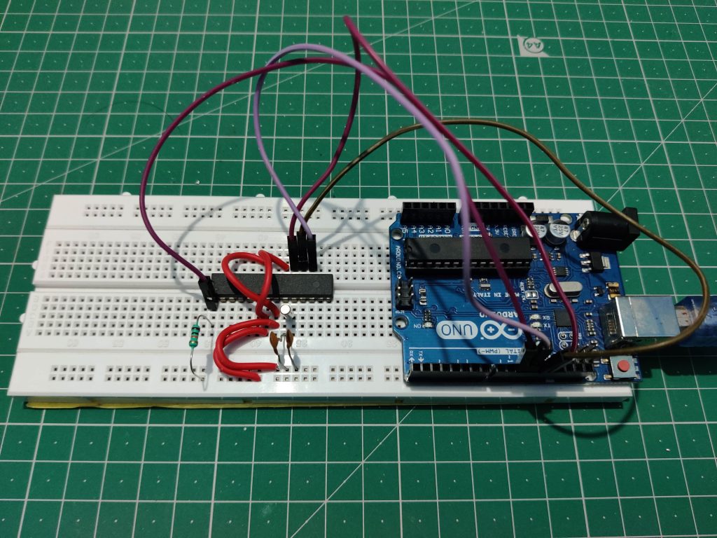
In this tutorial, you will learn how to upload a bootloader in a newly purchased ATmega328P IC, and upload code in ATmega328P, ATtiny85, and ATmega8 using Arduino UNO board.In some Arduino projects, you may only want to use the microcontroller IC(ATmega328P) instead of using the whole Arduino UNO board. In that case either you can […]