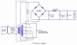
With the popularisation of PCs, the constant voltage transformers (CVTs) have also become equally popular. The CVT is simply a magnetic transformer of a special construction that has a capacitor connected across the secondary winding of the transformer. In an ordinary transformer, the primary and secondary windings are wound near each other so that whenever there is a change of voltage across the primary there is a corresponding change in the secondary voltage depending upon the ratio of the turns on the two windings. However, in a CVT the primary and secondary windings are wound separately from each other, as illustrated in figure. To set up field in between the coils, a separate shunt path is provided between the two windings but an airgap is formed in the shunt path. A capacitor is connected across suitable tappings of the secondary winding. The constructional details of a CVT are shown in the figure.

Operation of CVT.
The portion of the magnetic core over which the secondary winding is wound is saturated, while the portion over which the primary is wound is not saturated. A capacitor is connected across the secondary winding to tune out the output at a frequency very close to 50 Hz. This capacitor also makes the current in the secondary winding to increase which helps in the saturation of the secondary flux. Since the secondary ac flux is restricted to a saturated value for a large range of the input voltage (170-270 V), a constant voltage is available across the secondary winding. The output voltage will not be of a pure sinusoidal waveform but will be an approximate sinewave with the peaks flattened approaching a square wave. Output voltage waveform of a CVT is shown in figure. In figure, a compensating winding is shown connected in series to the secondary to improve the CVT performance.
If a CVT is placed at the output of a square wave inverter (in the UPS), care must be taken to control the frequency of the inverter, since the CVT is sensitive to the frequency of its input supply.
The reason we use a CVT and not a voltage stabilizer for computer applications is that in the voltage stabilizer relays are present and when these relays operate (switch), the output voltage may be interrupted for a short time. Such a transient may not be desirable for computers which may cause the computer to reboot. Also, the CVT provides a clean spike-free output voltage. The voltage regulation possible in a CVT also is good.
The input voltage ranges 170 to 260 V and output regulation is 230 ± 2 % at no load to full-load. Distortion-approximately 5% under full-load conditions. Rating of 50, 150, 250, 350, 500, 750, 1000, 2000 VA.
A practical circuit of a CVT power supply is given in figure.

18 Comments
I NEED 500VA TRANSFORMER DESIGN & CAPACITOR DETAILS.
hi sir i am interested in cvt design please send me design procedure and calculation of capacitor also.waiting for your reply.
if possible give me 1 design example also
we need a CVT design and example.
hi sir i am interested in cvt design please send me design procedure and calculation of capacitor also.waiting for your reply.
if possible give me 1 design example also
Hello
Kindly provide winding detail of resonent windind (number of turns ) also primary and secondary.
Thanks
Khurram farooq
What is the efficiency from no load up to 150% overload
Sirs,
I have a CVT which worked fine but now the out put has dropped to 215 volts?? Any possible suggestions?
Thanks
Please Provide me quotation for 5kva cvt
Hi, i’m looking for a CVT for a machine that we are going to install in India, we are from Mexico, so we dont know local market, do you know were I can find a provider for this equipment??
Thank you
If freq. level is change to 60hz means, CVT output also changed.
If we give 230v & 60Hz supply to the CVT, then it’s received output as 298v.
why this is happened,in case of 50Hz means it working fine
hey m designing a cvt ranges from 180v-250v of 50VA m getting a constant voltage across its o/p of 200v. actually i used a electromagnet in series with a capacitor and parallel with the primary.but when i am putting any load below 50va across the secondary it gives zero volt. plz if somebody knws smthn regarding tat help me out.N 1 more thng the connection m using z rt or not?because with the above shown circuit m not achieving even saturation.
Hi friend,
I think your site is very interesting for me, your site give me some important information about Voltage Transformer, thanks a lot for share these.
hi sir i am interested in cvt design please send me design procedure and calculation of capacitor also.waiting for your reply.
if possible give me 1 design example also