Description.
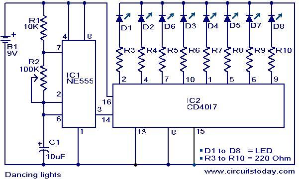
Here is a simple dancing light circuit based on NE555 (IC1) & CD4017 (IC2) . The IC1 is wired as an astable multivibrator to provide the clock pulses for the CD4017. For each clock pulse receiving at the clock input (pin14) of IC CD4017, the outputs Q0 to Q9 (refer pin diagram of CD 4017) becomes high one by one alternatively. The LEDs connected to these pins glow in the same fashion to give a dancing effect. The speed of the dancing LEDs depend on the frequency of the clock pulses generated by the IC1.
Circuit diagram with Parts list.
Notes.
- Assemble the circuit on a good quality PCB or common board.
- The ICs must be mounted on holders.
- The speed of the dancing LEDs can be adjusted by varying POT R2.
- The capacitor C1 must be rated 15V.
- Using different color LEDs could produce a better visual effect.
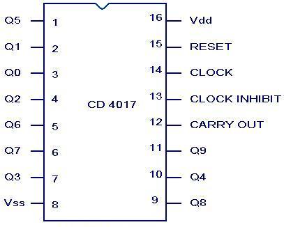
CD 4017 Pin configuration.
68 Comments
Hello Sir
I want use 1 Watts 5 to 6 Led with this circuit what changes I have to make.
please reply to me the details of using parts
can someone pls post the detailed picture of the connection in a more elabrative way… 😀
sir ,
i want coding part of this project complete details. i hope so ill get this by today evening
Dear sir,i want to increase the of led chaser 10 stage basded on 555 and 4017 chip. Please tell me about the transistor which can handle 12/1amp.
Use BC517 Darlington transistor as driver for CD4017
I have been working with the CD4017 and CD4060. Have noticed that both chips work quite well, but after a long period of
Time the chip will fail. After looking at the spec. Sheet the input voltage on all inputs is point 5 volts not 5 volts at .010 Amps and the outputs should be buffered with ULN2003AN a FET driver chip. LEDs will work on there outputs but after some longer period of time the chip will fail . So take my advice and be safe with your design.
Yes Mr Dennis you are correct, the IC can sink 2.5 mA and drive out level is 1mA. Hence a buffer transistor array is required for a reliable operation of the IC.
you know how to Access circuit in computer programing??
i am computer programmer
Using 4017 integrated circuit for running LED produce versatile circuit, the running speed is easily adjusted by changing the clock frequency, and the number of LED can be selected by connecting the last needed output to the reset pin. If you need simpler circuit using only 3 LEDs then discrete circuit using transistors can used
Hamuro, can you get in touch with me about this relay schematic?
Thanks!
plz tell well have R2 variable resistor or as potentiometer?
Hi Tabish it is used as a variable resistance, since pots are available freely its center tap is connected one end and used as a variable resistance.
it is a wonderful idea for youngstar
is this working,, may i see the video because i want to try it
What is the use of pin 12 and 13
My first and charming mini project… got o/p… Thank u..
sir ‘ i wanna combine this circuit so, can u send me its full working and equipments with suite matter.?
built this and worked fine.
then i built it again and now one led will work then when it trys to change to the next all 8 leds flash and it goes back to the same led,
anyone know what ive done wrong ?
I want to do this project so give me all the information about this project.plz..
i want MPLAB program for dancing light
good project
very simple
What if I want more than 9 leds , i.e can i connect two 4017 IC’s to timer 555 ? Doing this project please let me know .
I have visited many sites for this project. There are only 8 LED outputs in this schematic but in other sites they have given 10 LED outputs. Please say me the reason.
Hi you can use up to 10LEDs. output Q0 to Q9. Fixing the LEDs in a circular fashion dividing 360 deg by 10 will be 36deg will be difficult. for 8 LEDs 45deg easy to achieve. that will look nice and symmetrical.
Well, it IS working buddy…
i want to do this project so give some ideas…..
D circuit look very simple…but when i started working on it i was confuse…due to the numbering of the ic’s…ne555 and the cd 4017 numbering is xo wrong..imagine on the 555,7 and 2 are on d same side impossible 3 is on d other side…while on the 4017,no 10 can’t be on R6…Please give me the right number$..cause am still little confuse here…
any ic that is 4017.. CD and CF are just brand names.. 🙂
Hello,
What an eqivalent IC can be used instead of the CD4017 and CF4017 ?
@chitra:
Yes you can use
Can use IC CF 4017 Instead of CD 4017…
which IC is used here; CD4017BM or CD4017BC…..?
hi…this web site is very use full our studend genaration
i am like this circuit model
It will only costs rs 40…… It’s nice….. Please go with this for your project
It’s a nice one ..i loved it..please post some other similar circuits…….
i have designed this circuit on a breadboard and when i connect the dc supply to it only one led glows and when i m about to take out the the pins of the supply the the leds start moving…..can any help on this….
Check ur capacitor .. it might not be connected properly or might be shorting intenally …. if problem continues then replace ur 10 micro capacitor with 1micro and connect 10micro between ground and vcc and connect a resistor or potentiometer between pin 6 of 555 and r2 …. if u choose to connect potentiometr then u will be able to vary the speed of led also
we take a project of dancind lights as a semester final project .
me n my friend want to do this in super way.kindky guide me that what we’ll made n how?
m waiting 4 ur help
If you want to use a NPN 2N3904 Transistor you must do the Following 1) Switch collector and Emitter Connections Around and 2) Switch Led’s around I used 2N3906 because that is all i had at the Time,,I breadboarded both designs and they just worked fine,,,HAPPY BUILDING!!!
I designed one of these circuits years ago and added a transistor Current Amplifier to increase the brightness level of the led’s, Pin 2 of the 4017 feeds a base of PNP Transistor. The Emitter of the PNP Transistor is connected to the 220 ohm resistor which in turn connects to the +9 volt side of the battery. Now the collector connects to the anode of the LED while the cathode of the LED goes to -9 volt side, The Emitter of the PNP Transistor goes to one side of the 220 ohm resistor while the other side of the resistor goes to +9 volts,,, repeat the same circuit for 4017 pins 4,7,10,1,5,6 and 9,if we can improve on a GREAT CIRCUIT,,Why Not??? This is a Fun Circuit,,Thanks!!! PS*** I used a 2N3906 Transistor
Please give the simple circuit of a christmas light
jhakkkas yar mera project to chal pada, maja aa gaya.
The circuit is hardly a dancing lights. This circuit is more appropriately can be called decade light chaser o running lights.
what is the use of the capacitor??
very nice circuit.
Hi Rajesh you can connect red, green or yellow LEDs 4nos in series with 47ohms resistance instead of 220 ohms. white or blue LEDs you can connect 2nos in series with 39 ohms resistance. if you want larger number of LEDs to be used then connect of the base a transistor to LM4017 out put emitter to common negative rail, with open collector then you can connect series parallel etc.
Sir,
can i increase the number of LED’s up to 30 or 40? i can’t get the ans of >( Kiran, you can use up to all 10 outputs of 4017, Q0 to Q9)
pls clarify
Hi Abhishek you can check shifting of LED glow. disconnect the connection between Pin 14 of IC2 to Pin 3 of IC1. connect a 10K resistance to Pin14 of IC 2. Connect other end of resistance to + voltage. every time you touch + with resistance the LED glow should shift from first to net etc. if this happens your NE555 circuit is faulty. if LEDs are not glowing at all check LED polarity and supply to IC2.
hi i have made this project but not working
Dear sir, I want the circuit diagrma of LED Music Control Ligh. I have seen the video of the same on YouTube. The URL is http://www.youtube.com/watch?v=DMH-xKpHLxg.
Can you please provide me the same circuit. Please informe me via mail to vspersonal1999@gmail.com
With Regards.
sir I want to have 30 led dancing light with 2 or 3 ways changing …..please give me details about the circuit and IC’s
hi I need for yours help. first i am explain my project. we have a bike(with self motor). just i put the key and i said to my bike “engine start”. this only recognize my voice. others telling not work. this is my condition anybody can help me?
hi this hajiali i am making e light name of sagar light india i am planing to make led light
Hi Kiran you can use up to all 10 outputs of 4017, Q0 to Q9.
Hi Romeo you can use for chasing light.
can I used this circuit if I make a circuit in which name or item running in a board?
dear seetharaman sir,
can i increase the LED’s more than 8 nos ,is there any changes in circuit? sir please guide me ,waiting for your positive reply.
its nice useful to
Hi my name is amit. I want to do work on this project plz help me…does it realy work.and how much money we want to cmplet this.
not able to understand briefly.plz able to give clear explanation so that i will be able to submit this dancing lights as my project
i make this dancing leds as my project………..
But it is not working
Hi Pinaj check your wiring. use 9 volt 300mA power pack for the supply. Increase R3 to R10 to 68 ohms so that the LED current is limitted to 10mA. To check the circuit by part. Check by feeding high signal to Pin no 14 of CD4017 by disconnecting the clock pulse from 555. The LEDs glow should shift from LED 1 to LED 8. If this is OK then the fault is in the clock. Check whether Pin 8 Vss is conected to negative and Pin 16 Vdd is connected to positive.
its too nice yaar.
I am making this project in my college
I need to make something like this..I am a newbie please tell me where to get these parts for dancing lights?
Nice One, I liked it !!
sir want to have 60 LED dancing light with 15 ways changing. so can you give me the details of ic and curcuit diagram….
sir please please reply fast i am having 10 days to complete my project please help me.