Description.
The dark detector circuit shown here can be used to produce an audible alarm when the light inside a room goes OFF. The circuit is build around timer IC NE555. A general purpose LDR is used for sensing the light. When proper light is falling on the LDR its resistance is very low. When there is no light the LDR resistance increases. At this time the IC is triggered and drives the buzzer to produce an alarm sound. If a transistor and relay is connected at the output (pin3) of IC1 instead of the buzzer, electrical appliances can be switched according to the light.
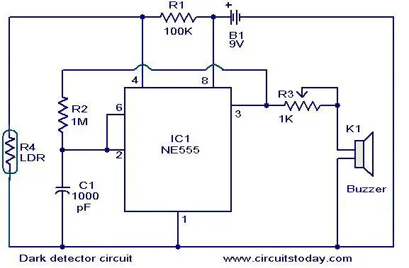
Circuit diagram with Parts list.
Notes.
- The LDR ,R4 can be any general purpose LDR.
- The circuit must be assembled on a good quality PCB or common board.
- The circuit can be powered from a 9V PP3 battery.
- The POT,R3 can be sued as a volume controller.
- Mount the IC1 on a holder.It will make replacements easy.
44 Comments
Hi
I have to get the Dark detector circuit for my sons elektrical klass. Where can I bay one?
Thank you.
Ninettte
Dear sir,
In this circuit, you used 1000pF capacitor. Is the capacitor CERAMIC or ELECTROLYTIC?
If I use 1kilo-ohm resistance instead of the 1k-pot, will the circuit function?
can we use led instead of alarm to use it for lightening in the dark?
can we use duracell battery instead of PP3 battery..??
Sir, mine always sounds whether there is light or there is not. PLEASE HELP
May be your LDR is not OK with sufficient range. Try increasing the value of R1 from 100 k to 220 or 470 k, if it is still not become alright try by replacing LDR with different make or diameter.
sir, how the circit
turn off
excuse me sir.. what pin of the relay should be connected to pin 3. and also where will i connect the diode before placing the relay.. thank you
or i should say instead of the diode ..what transistor is needed to place before the relay?
muhamad ahsan;
i realy don’t know about this project but i love to hear the voice of buzzer.
Hi Kiran you can. you may have to slightly alter the value of R1. the sound from the Buzzer will be very low.
hi can i use a 6 volts 4.5ah battery?
thank u very much sir.’;
Hi arc 104 is 0.1uF (100,000PF) 102 is the correct capacitor. Since the capacitor value is quite high the IC generates squarewave output. Reduce capacitor C1 value and add a 100uF 16volt capacitor across the relay to improve further.
There is no need for any additional transistor to drive the relay as this IC is capable of 200mA drive output.
susan, a relay is a switch operated by electricity. relays can be driven with a range of 6-24 volts direct current @0.5-2 amperes. the coils of the relay is where you plant the power;.’ you can connect the polarities of the power supply to the coils either way;’ relay, like other switches is classifies by their poles: SPST, SPDT and DPDT. mainly, it is an electromechanical device which is also known as electronic switch;.’
what is relay?
i tried the design as well and i used a 104j mylar cap for c1 1000pf. i did not find a 1m resistor so i used a 1.2m and connected a relay w/c could be driven with a supply from 8-12v i planted the diode across the relay coils yet with or without the presence of light, the relay still goes crazy. it simultaneously switches on and off and i never planted the pot. i even cut off the ldr and i get same results. sir, pls help. what could possibly went wrong?
which transistor should be used to connect relay??
hey..
what is the function of NE555 in the circuit?
can you also tell me what is the capacitor used for?
I Like Circuit too…OVAISHAMDANI!!!!!
This circt has a bit confusion … I have a simple solution for this …. Hmmm just connect ldr’s 1pin on grnd n second on ic’s 2,6 … N use a prest of 20kr n connet it between vcc n 2,6 … Dun forget to use 100nf’s ceramic capacitor on pin 5 ……… It will really work … I tried
Ovais hamdani
I used this circuit as a security system . 555 ic is great . I made lot of projects on that … Nw m doing diploma n just want to learn assembly language … If u have any curies plz ask to me i like to talk on elctronics … Search me on fb ‘hamdani ovais’ iz my username hope sme1 ll contact to me … Ovais
i dear i wanna make a human detector circuit by using 555 ic can u help me
hi is this working?
Hi Subham you can use in both ways. light activated / dark activated by interchanging the no / nc contacts of the relay.
i think it is like light activated switch. . . . . . bcoz when we connect to relay (NC) it acts like a dark activated switch. . . .isn’t it? ? ? ?
Hi Abdullah NE555 can drive up to 300mA load. So you can use a power relay in the place of Buzzer remove variable resistance volume control donot forget the freewheeling diode across the relay coil. and connect any load through its contact. When you cover LDR the resistance will go high and voltage at Pin 4 will go high the out put of NE555 will go high hence the relay will come on, you may use an LED with 1K resistance in series in parellel to the relay as an indication..
hi sir
iremove the buzzer and i put transistor , RLL and light
note : the light is on and off when i coverd the ldr ( no light high ressistor
What are the possible transistor and relay that can be replaced instead of the buzzer?
yes
Yes https://www.circuitstoday.com/wp-admin/edit-comments.php#comments-form