In this article, we are going to control two motors by using the GY-521 accelerometer module. The speed of the motor will increase or decrease upon moving the GY-521 module up or down. On moving the Gy-521 towards the downside, the speed of the first motor will decrease and the speed of the other motor will increase; while on moving the GY-521 towards the upward side, the speed of the second motor will decrease and the speed of the first motor will increase.
Before we begin our tutorial on controlling the motor speed, let’s see how to interface an accelerometer to Arduino.
Components Required
The components required for this project are as follows
- Arduino
- L293D Motor driver IC
- GY-521 Module
- 2 DC Motors
- 7-12V battery
- Breadboard
- Connecting wires
Circuit Diagram

First of all, make the connections of the L293D with the Arduino as follows
- Connect the pin 1 of the L293D IC to the 5V of Arduino.
- Connect the pin 2 of L293D to the digital pin 5 of the Arduino.
- Connect the pin 3 of the L293D to one end of the motor and connect the other end of the motor to the pin 6 of L293D.
- The Pins 4, 5 are the ground pins, connect these to the GND of Arduino.
- Connect the pin 7 of L293D to the digital pin 6 of Arduino.
- Pins 8 and 16 are the VCC pins, connect these to positive of battery and connect the negative of battery to the Ground.
- Connect the pin 9 of L293D to the 5V of Arduino.
- Connect pin 10 of L293D to the pin 9 of Arduino.
- Connect pin 11 of L293D to the one end of motor and connect the second end of motor to the pin 14 of L293D.
- Pins 12 and 13 are the ground pins, connect these to the ground.
- Connect pin 15 of L293D to the pin 10 of Arduino.
If you are using any Arduino other pins for making connections to the L293D motor driver, then ensure that you select PWM enabled pins.
After that, make the connections for the GY-521 module with the Arduino as follows
- VCC pin of GY-521 to the 5V pin of Arduino
- GND pin of GY-521 to the GND of Arduino
- SCL pin of GY-521 to the A5 of Arduino
- SDA pin of GY-521 to the A4 of Arduino
Working
The structure of the accelerometer sensor has a mass attached to a spring which has fixed outer plates and moves along one direction. So when an acceleration is applied in any of the direction, the capacitance between the plates and the mass will change. The accelerometer sensor will measure this change in capacitance which corresponds to an acceleration value.
On moving the GY-521 in the upward or downward direction, the sensor will give us output from -17000 to +17000. We will map this from -125 to +125 and will use this value to rotate the motors. Now, when we move the GY-521 towards up, the output value will go to 125. We will add 125 to this output value and this will be the speed of the first motor. Similarly, when we move GY-521 towards the downside, the output value will go to -125. We will subtract this value from 125 and this will be the speed of the second motor.
Program/Code
#include <Wire.h>

#include <MPU6050.h>
#define motor1_pin1 5

#define motor1_pin2 6

#define motor2_pin1 9

#define motor2_pin2 10
MPU6050 gy_521;
int16_t ax, ay, az;
int16_t gx, gy, gz;
int motor1_speed;
int motor2_speed;
void setup ( )
 {
Wire.begin( );
Serial.begin (9600);
Serial.println ("Initializing MPU and testing connections");
gy_521.initialize ( );
Serial.println(gy_521.testConnection( ) ? "Successfully Connected" : "Connection failed");
delay(1000);
Serial.println("Reading Values");
delay(1000);
}
void loop ( )
 {
gy_521.getMotion6(&ax, &ay, &az, &gx, &gy, &gz);
ax = map(ax, -17000, 17000, -125, 125);
motor1_speed = 125+ax;Â Â Â //To move first motor
motor2_speed = 125-ax;Â Â Â //To move second motor
Serial.print ("Motor1 Speed = ");
Serial.print (motor1_speed, DEC);
Serial.print (" && ");
Serial.print ("Motor2 Speed = ");
Serial.println (motor2_speed, DEC);
analogWrite (motor1_pin2, motor1_speed);
analogWrite (motor2_pin2, motor2_speed);
delay (200);
 }
Code Explanation
First of all, we included the libraries for communicating the GY-521 module with the Arduino. The GY-521 module works with the Arduino through the I2C communication so we have included the wire library which allows the I2C communication between the Arduino and the GY-521 module.
#include <Wire.h> #include <MPU6050.h>
After that, we defined the pins where we connected the motors.
#define motor1_pin1 5 #define motor1_pin2 6 #define motor2_pin1 9 #define motor2_pin2 10
Then we read the values of x, y and z axis from the GY-521 and converted the x-axis values from -125 to 125 to move both the motors. When we move the GY-521 toward up, then the ax value will go to 125. We will add 125 to it and this will be the speed of the motor 1. When we move the GY-521 towards down, then the ax value will go to -125. We will subtract this value from 125 and this will be the speed of motor 2.
gy_521.getMotion6(&ax, &ay, &az, &gx, &gy, &gz); ax = map(ax, -17000, 17000, -125, 125); motor1_speed = 125+ax;Â Â Â //To move first motor motor2_speed = 125-ax;Â Â Â //To move second motor
Then we will print the Motor1 speed and Motor2 speed on the serial monitor and also we will rotate the motors using the analog write command.
Serial.print("Motor1 Speed = ");

Serial.print(motor1_speed, DEC);

Serial.print(" && ");

Serial.print("Motor2 Speed = ");

Serial.println(motor2_speed, DEC);

analogWrite(motor1_pin2, motor1_speed);

analogWrite(motor2_pin2, motor2_speed);
So that’s all! We have successfully interfaced accelerometer with Arduino and then controlled motor rotation.
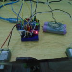
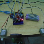
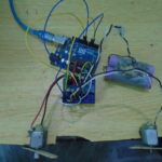
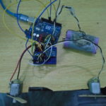
Output Photograph