How to control DC motor speed using PWM on Atmega32
Using PWM (Pulse Width Modulation) to control a device is a common practice in embedded systems; for example, you can use it to control the light intensity of a LEDÂ or control the speed of a DC motor.
In this article, we will explain how to get a PWM from the AVR Atmega32 and we shalll apply the output PWM to a small DC motor to vary its speed.
In order to get the PWM from AVR, we need to use the timer/counter module of the AVR. This module can be used in several modes to generate different PWM signals of different characteristics; here we shall explain how to use the counter in the “Phase Correct PWM†mode. Atmega32 has 3 timer/counters and we are using timer/counter 0.
In “Phase Correct PWM†mode, the counter counts repeatedly from 0 to its maximum value (0xFF) and then back from the maximum to zero. The Output pin (OC0) is cleared when the counter reaches a certain value called the “Compare value†while up counting, and is set when the counter reaches the same value while down counting. This compare value is set by the software in a register called OCR0 (Output Compare Register), while the value of the counter itself is contained in a register called TCNT0.
When the value of TCNT0 matches the OCR0, it’s called a Compare Match. The below timing diagram explains the operation.


You can also invert the output PWM by changing the values of bits (COM00 and COM01) in the TCCR register. In that case, the Output pin (OC0) is set when compare match occurs while up counting, and is cleared when compare match occurs while down counting, and the waveform will be as shown in the timing diagram below.

In this case, we can calculate the PWM duty cycle using this equation:

In this article, we will use 3 different duty cycles by changing the compare value (OCR0) based on the push buttons pressed by the user and we shall notice the change in the motor speed.
Let’s get first to configuring the PWM, this is done in 2 simple steps:
- Configure the TCCR0 register.
- Set the compare value in the OCR
-
Configuring the TCCR0 Register
| W | R/W | R/W | R/W | R/W | R/W | R/W | R/W |
| FOC0 | WGM00 | COM01 | COM00 | WGM01 | CS02 | CS01 | CS00 |
- Set bits WGM00 and WGM01 to 1 and 0 respectively. This enables the phase correct PWM mode.
- Set bits COM00 and COM01 to 0 and 1 respectively. This means that the generated PWM will be an inverted PWM.
- Set bits CS00 and CS01 and CS02 to 1, 0 and 1 respectively. This means that the counter will be clocked from the system clock divided by 1024.
2.  Setting the compare value in the OCR register
As mentioned above the duty cycle is calculated using this equation
So setting OCR0 =178 will result in a PWM with around 30% duty cycle.
Setting OCR0=102 will result in a PWM with around 60% duty cycle.
Setting OCR0=25 will result in a PWM with around 90% duty cycle.
In our program, we will do the following:
- Read 3 push buttons connected to PORT D pins (0, 1 and 2).
- If button 1 is pressed, we will set OCR0=25 i.e Duty Cycle is 90%  – The motor will spin at high speed
- If button 2 is pressed, we will set OCR0=102  i.e Duty Cycle is 60% – The motor will spin at a medium speed
- If button 3 is pressed, we will set OCR0=178  i.e Duty Cycle is 30% – The motor will spin at low speed
And we shall watch how the motor speed will vary.
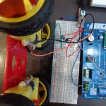
DC Motor

When connecting a DC motor to an MCU, we shouldn’t power the motor from one of the MCU pins as the high current and electric voltage surges of the motor may damage the MCU. Instead, we should connect the motor to a power supply and then switch the power supply (turn On/Off ) to the motor by applying PWM to the base of a Darlington transistor (usually called as the motor driving transistor). This way the motor speed varies according to the duty cycle of the PWM. The whole circuit connection is demonstrated in the below schematic. Note that the OC0 pin is on PB3 (Port B, pin3)
Note : – The OC0 pin is on PB3 (Port B, pin3)
Circuit Diagram – PWM in AVR Atmega32

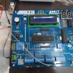
Finally here is the program code, circuit pictures and a video showing the circuit operation.
Program/Code – DC Motor Speed Control using PWM in AVR
#include <avr/io.h>

#define get_bit(reg,bitnum) ((reg & (1<<bitnum))>>bitnum)

int main(void)

{

   DDRD=0b11111000; // set the first 3 pins of PORTD to be inputs to read from the push buttons

    DDRB=0b11111111; // ensure that Pin3 in POrt B is output as this is the OC0 pin that wll produce the PWM.

    PORTD=0b00000000; // Initialize PORTD to zeros

    TCCR0=0b01110101; //Configure TCCR0 as explained in the article

    TIMSK=0b00000000;

    OCR0=255; // Set OCR0 to 255 so that the duty cycle is initially 0 and the motor is not rotating

       while(1)

    {

       if (get_bit(PIND,0)==1)

       {

              OCR0=178; //If button 1 is pressed, set OCR0=178 (duty cycle=10%).

       }

       if (get_bit(PIND,1)==1)

       {

              OCR0=102; //If button 2 is pressed, set OCR0=102 (duty cycle=60%).

       }

       if (get_bit(PIND,2)==1)

       {

              OCR0=25; //If button 3 is pressed, set OCR0=25 (duty cycle=90%).

       }      }  }
Demo Photographs
Demonstration Video
So we finished our tutorial on How to control DC motor speed using PWM in AVR Â Atmega32. If you have any doubts, ask in comments.
hello friend i need to program something like this on an atmega 328 in atmelstudio the task is to control an 24v dc motor using pwm and two buttons to decrease and increase speed. can you help me write the code? if it works like it should i would even pay you.
greetings!
Hi
I’m using AVR with ATmega32 to control 2 DC Motors together with 4 Push-buttons
But I can’t handle with the motor speed with OCR0
So .. I want to control with PWM with OCR0 like this article
please I want to ask questions
1. can we use any mode of timer to control the speed of motor like overflow mode ?
2. why here we didn’t use the TCNT0 register which we will compare the value in OCR0 with the value in TCNT0 ?
what is your MCU clock speed?