In this article, our author Mithun has developed a 0 – 99 min counter using PIC microcontroller 16F628A. So basically this is a digital count down timer ideal for engineering and diploma students for their project requirements. We have given complete circuit diagram of the digital count down timer along with full source code. In addition, photographs of the breadboard setup is uploaded.
Every micro controller has a timer unit inside. A timer is nothing more than a time counting device fabricated inside the micro controller unit. A wide range of practical applications require a timer in action. For example, we need to turn a motor ON for 5 minutes and then turn it OFF as part of a particular project; how will we do that? A timer inside a mircocontroller unit aids us in implementing this perfectly. A timer can be used to count the 5 minutes exactly and the bits that get SET at 5 minutes limit can be used to program the controller to turn OFF some device(s).
I hope you got a basic idea about timer unit and its practical applications. We are going to make this project using an LCD display, PIC controller 16F628A and a 4 MHz external crystal to provide the necessary clock. We will be writing the codes using micro C.
In any project that involves an LCD, the first step is to initialize the LCD module. We have written detailed articles about interfacing LCD to an MCU before. You can learn more about Interfacing an LCD to 8051 and Interfacing LCD module to AVR controller in these articles. If you want to learn more about character LCD displays in detail, this tutorial on Character LCD displays will be of help.

Now, we need to configure relay and switches. The code snippet for the same is given below.
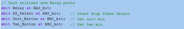
Here ‘sbit’ stands for set bit. You can do the same another way using “#define” command. This line means that RA3 pin will be known as the Relay/ RB0 pin will be known as SS_Select etc.
Even though the project name “digital count down timer” sounds so silly, its operation is not that simple. We have given below a proteus diagram of the circuit to explain the project perfectly.

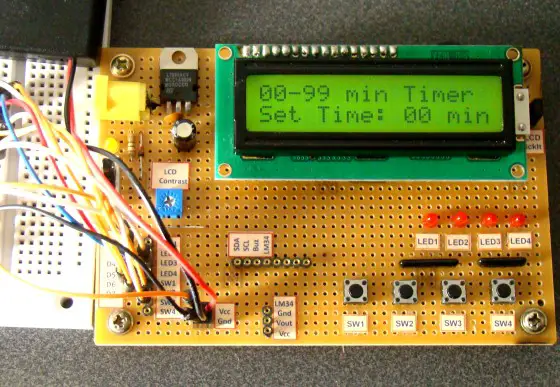
Analyzing the circuit diagram, you can see three buttons . One button is for Start/Stop function and the other 2 buttons for Units & Tens counting. We will configure our LCD module with display messages corresponding to the button configurations.
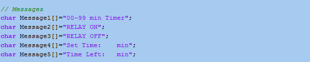
These are the messages we will be showing in our LCD. To control the system we’ll need some other variables as well. These variables are declared in the code snippet given below.
![]()
Lets understand the counting mechanism now. The circuit is wired in such a way that, the user will have to select the limit of counting initially. If the user is interested in counting 1 to 9 minutes only, then he is supposed to press the units button alone. If he is interested in counting 1 to 99 minutes, then he should press the Tens button along with Units button. Once he sets the limit, he should press the Start/Stop button to start the timer (its a push button switch and same button switch is used to stop the timer as well).
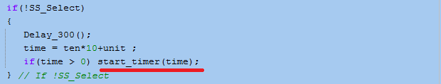
Note:- Since the timer operation depends upon the value selected by user (units and tens switch), we have to check certain possible error conditions before starting the timer. Assume a condition in which the user forgot to select units or tens switch and pressed the start/stop button directly; what is supposed to happen in this scenario? It’s an expected error condition that should be handled inside the software. A common way to handle this scenario is to start the timer only if the limit value is greater than zero. The code snippet given below handles this condition.
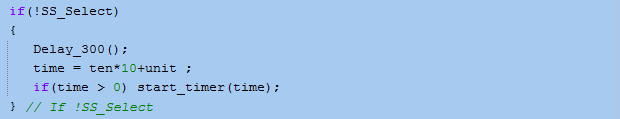
I hope you understood the code snippet well. The timer will start only when the given limit value is greater than zero. This condition is checked every once the SS_select button (Start/Stop button) is pressed.
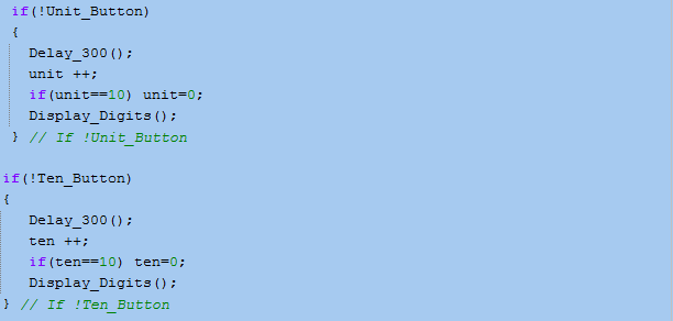
How those two buttons function is very simple. Each press on the ‘units’ button increments the unit variable by 1; upon exceeding 9 its value gets reset. Similarly ‘tens’ button increments by units of 10. The function Display_Digits( ) is a subroutine to display the numbers in LCD. You can see the code snippet of Display_Digits() subroutine below.
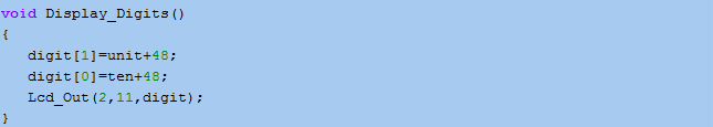
The digits are displayed in the Line 2, column 11 of the LCD display. This is executed by code line: Lcd_Out(2,11,digit);
If you have noticed a function named start_timer(time); it’s the subroutine to control the time. So lets see the function.
“void start_timer(unsigned short MinVal)
{
unsigned short temp1, temp2;
Relay = 1;
ON_OFF = 1;
Lcd_Cmd(_LCD_CLEAR);
Lcd_Out(1,1,Message2);
Lcd_Out(2,1,Message5);
OPTION_REG = 0x80 ;
INTCON = 0x90;
for (i=0; i<MinVal; i++)
{
temp1 = (MinVal-i)%10 ;
temp2 = (MinVal-i)/10 ;
Lcd_Chr(2, 12, temp2+48);
Lcd_Chr(2, 13, temp1+48);
j=1;
do
{
Delay_ms(1000);
j++;
} while(((j<=60) && (Clear ==0)));
if (Clear)
{
Relay = 0;
Delay_ms(500);
Lcd_Out(1,1,Message3);
INTCON = 0x00;
goto stop;
}
}
stop:
Relay = 0;
ON_OFF = 0;
unit = 0;
ten = 0;
clear = 1;
}
void interrupt(void)
{
if (INTCON.INTF == 1) // Check if INTF flag is set
{
Clear = 1;
INTCON.INTF = 0; // Clear interrupt flag before exiting ISR
}
}”
This subroutine does the basic time calculation that is necessary in making the timer. You can understand this sub routine easily if you know more about the registers OPTION_REG & INTCON
The images given below are screenshots taken from the datasheet of PIC16F628A. Skim through it to get a detailed idea of the registers involved.
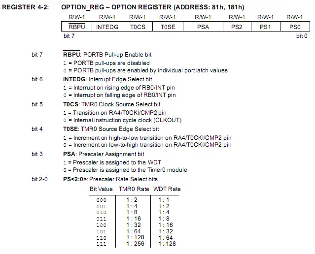
In our program, OPTION_REG = 0x80; that means: 0b1000 0000; bit 7 is 1, and other bits are 0.
And the INTCON register is:
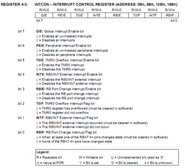
In our program, INTCON = 0x90; and when timer exceeds its set limit its 00.This means we are starting the interrupt when the timer starts running and when it exceeds the set value, we are making all interrupts disabled.
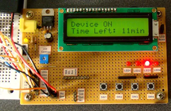
We use the relay to turn ON when time is set and at times when user presses Start/Stop button. The same relay is turned OFF when timer reaches/exceeds its set value.
Here is a a set of hardware implementation of this project.
Source Code
We have provided complete source code for this digital count down timer project here. You can download the source code by using the link given below.
Download the Source Code [Digital Count Down Timer]
Note:- I hope you all understood the project really well. If you have any doubts please feel free to ask in comments section.
17 Comments
Starting header file with full continuous source code for 8051 microcontroller
Timing ranges (0-120minutes) or more than 120minutes
dear ,i need a timer for exact to one min,and that count should display on lcd like 60,59,58,57…….,00
can u help for working with thisss plz
please tell me were i can place buzzer so that it beeps when timer is over
Hi,
Thanks for sharing the code and this project.
I wanted to get one clarification. Why it the Timer0 used in this code?
Since OPTION_REG = 0x80, the Timer0 interrupts every 512uSec (Pre-scaler = 1:2). In the ISR, “Clear” flag is Set. So after every 1 second Relay will be turned off and Message3 will be displayed.
Please correct me if my understanding is wrong
Hi Sir,
Is it possible to replace the lcd with 7 segment display…If yes,can sir guide me thru on how to construct that circuit.
Thanks
Hi,
Could you tell me how to modify the code to get a timer that countsdown from 30 secs to 0 secs please?
Thank you!
Hi!
I was wondering if I can make this count not in minutes, but in seconds? what shall I do? how will the code work?
thank you in advance 🙂
PS: this one is the right email :))
Hi!
I was wondering if I can make this count not in minutes, but in seconds? what shall I do? how will the code work?
thank you in advance 🙂
Sir can I get the proteus file of the timer project.
Please help please!!!!
I am doing a project named three phase motor soft starter. So I need help of a program to set starting time,starting current,stopping time and current.
I am using pic16f877 push_buttons lcd display and relays
very detailed analysis. Thank you.
Hi
Could you tell me how to modify the code to get a timer that countsdown from 20 secs to 0 secs please.
Urgent!
Dear sir,
I need 000.0sec – 999.9sec 7segment led disply delay and on timer. This timer working method is when input start switch on means fist delay timer run when delay time finish then start the on timer same time one output need. when input start switch off, timer goes to stanby as a set value. help me please thank you
does “sbit” stand for set OR single bit.
In your final picture I see a number of additional components that have been added. In example, the LCD contrast pot., the lcd backlight pot., the power jack connector, two additional switches, LEDs…..
I was just hoping maybe you could ellaborate on the additional code needed to add these components? Possibily even a really quick circuit schematic? I feel like these additional components really add the “Bells and Whistles” effect.
I have been tasked with providing a similar circuit for work and this is perfect! I will not take any credit away from you and your website, and will certainly not claim it as my own.
I want to thank you for providing your time and hardwork on this circuit and code. Placing it for free, on the internet, for the general public is very honorable. Kudos!
Dears,
I need to try in home so what are materials have to purchase and what to do?
please help me i am more in interest in small applications in our electrical application
Thanks and Regards,
P.Sivanpandi
It is very useful for my project.
Thank you very much