Contactless digital tachometer using 8051.
A three digit contact less digital tachometer using 8051 microcontroller which can be used for measuring the revolutions/second of a rotating wheel, disc, shaft or anything like that is introduced in this project. The tachometer can measure up to a maximum of 255 rev/sec at an accuracy of 1 rev/sec. What you just need to do is to align the sensor close to the reflective strip (aluminium foil, white paper or some thing like that) glued on the rotating surface and the meter shows the rev/sec on the display. The circuit diagram of the digital tachometer is shown below.
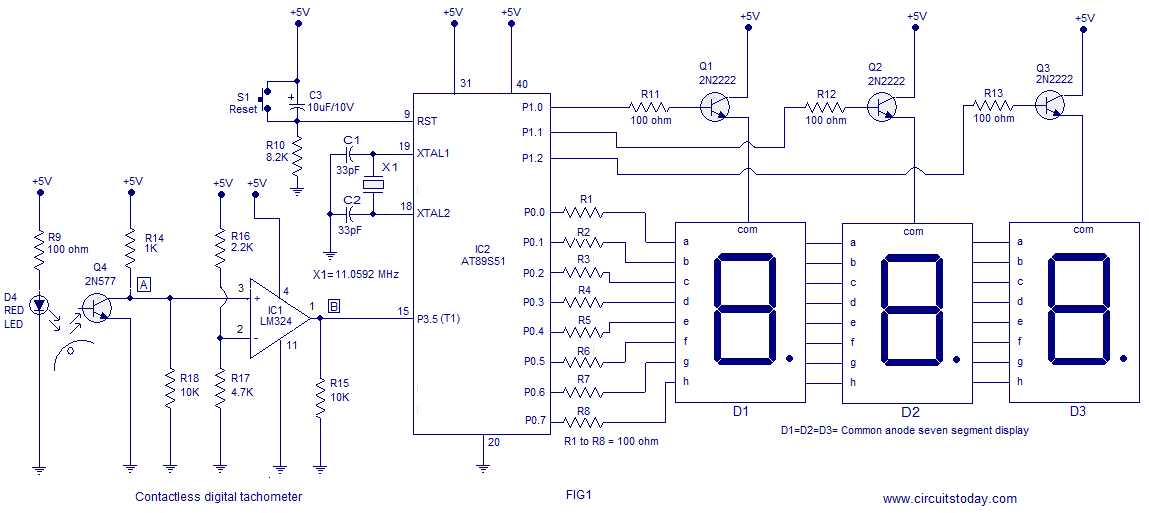
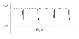
The first section of the circuit is the optical pickup based on photo transistor Q4 and red LED D4. Every time the reflective stripe on the rotating object passes in front of the sensor assembly, the reflected light falls on the photo transistor which makes it conduct more and as a result its collector voltage drops towards zero. When viewed through an oscilloscope the collector waveform of the photo transistor Q4 (2N5777) would look like this:
 Next part is the signal conditioning unit based on the opamp LM324 (IC1). Only one opamp inside the quad LM324 is used here and it is wired as a comparator with reference voltage set at 3.5V (using resistors R16 and R17). The job of this comparator unit is to convert the spiky collector wave form into a neat square pulse train so that it can be applied to the microcontroller. Every time the collector voltage of the photo transistor goes below 3.5V, the output of the comparator goes to negative saturation and every time the collector voltage of the photo transistor goes above 3.5V, the comparator output goes to positive saturation resulting in a waveform like this:
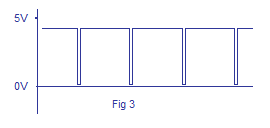
From the above two graphs you can see that the negative going edge of the waveform indicates the passage of the reflective patch across the sensor and that means one revolution. If you could some how measure the number of negative going edges occurring in one second, then that’s the rev/sec of the rotating object and that’s what the microcontroller does here.
The 8051 microcontroller here does two jobs and they are:
1) Count the number of negative going pulses available at its T1 pin (pin15).
2) Do necessary mathematics and display the count on the 3 digit 7 segment display.
For the counting purpose both the timers of 8051 (Timer0 and Timer1) are used. Timer 1 is configured as an 8 bit auto reload counter for registering the number of incoming zero going pulses and Timer0 is configured as a 16 bit timer which generate the necessary 1 second time span for the Timer1 to count.
Program.
ORG 000H
MOV DPTR,#LUT              // moves the addres of LUT to DPTR
MOV P1,#00000000B          // Sets P1 as an output port
MOV P0,#00000000B          // Sets P0 as an output port
MAIN: MOV R6,#14D
      SETB P3.5
      MOV TMOD,#01100001B  // Sets Timer1 as Mode2 counter & Timer0 as Mode1 timer
      MOV TL1,#00000000B   //loads initial value to TL1
      MOV TH1,#00000000B   //loads initial value to TH1
      SETB TR1             // starts timer(counter) 1
BACK: MOV TH0,#00000000B   //loads initial value to TH0
      MOV TL0,#00000000B   //loads initial value to TL0
      SETB TR0             //starts timer 0
HERE: JNB TF0,HERE         // checks for Timer 0 roll over
      CLR TR0              // stops Timer0
      CLR TF0              // clears Timer Flag 0
      DJNZ R6,BACK
      CLR TR1              // stops Timer(counter)1
      CLR TF0              // clears Timer Flag 0
      CLR TF1              // clears Timer Flag 1
      ACALL DLOOP          // Calls subroutine DLOOP for displaying the count
      SJMP MAIN            // jumps back to the main loop
DLOOP: MOV R5,#100D
BACK1: MOV A,TL1           // loads the current count to the accumulator
       MOV B,#100D
       DIV AB              // isolates the first digit of the count
       SETB P1.0
       ACALL DISPLAY       // converts the 1st digit to 7 seg pattern
       MOV P0,A            // puts the pattern to Port 0
       ACALL DELAY         // 1mS delay
       ACALL DELAY
       MOV A,B
       MOV B,#10D
       DIV AB              // isolates the secong digit of the count
       CLR P1.0
       SETB P1.1
       ACALL DISPLAY       // converts the 2nd digit to 7 seg pattern
       MOV P0,A
       ACALL DELAY
       ACALL DELAY
       MOV A,B             // moves the last digit of the count to accumulator
       CLR P1.1
       SETB P1.2
       ACALL DISPLAY       // converts the 3rd digit to 7 seg pattern
       MOV P0,A
       ACALL DELAY
       ACALL DELAY
       CLR P1.2
       DJNZ R5,BACK1       // repeats the subroutine DLOOP 100 times
       RET

DELAY: MOV R7,#250D        // 1mS delay
 DEL1: DJNZ R7,DEL1
       RET

DISPLAY: MOVC A,@A+DPTR    // gets 7 seg digit drive pattern for current value in A
         CPL A             //  (See Note 1)
         RET
LUT: DB 3FH                // Look up table (LUT) starts here
     DB 06H
     DB 5BH
     DB 4FH
     DB 66H
     DB 6DH
     DB 7DH
     DB 07H
     DB 7FH
     DB 6FH
END
Notes.
1) The LUT used here was made for a common cathode seven segment display (used in previous projects) and here we are using a common anode display. The instruction CPL A will just complement the digit drive pattern in accumulator so that it becomes suitable for the common anode display. This is done just because to save my time but not a text book method. The correct way is to make a dedicated LUT for common anode configuration and aviod the extra CPL A instruction.
2) LM324 is a quad opamp and only one opamp inside it is used here. I used LM324 just because that was the only single supply opamp with me at the time. You can use any single supply opamp that matches our supply voltage(5V). You can even use a dual supply opamp (like the popular 741) in single supply mode (+V pin connected to positive supply and -V pin connected to ground) but i wont recommend it unless you have an oscilloscope. Dual supply opamps configured in single supply mode will not give results like a dedicated single supply opamp in the same situation.
3) As we saw earlier the Timer 0 which generates the 1 second time span is configured in Mode 1 (16 bit timer). So the maximum it can count is 2^16 and that is 65536. In 8051 the crystal frequency is divided by 12 using an internal network before applying it as a clock for the timer. That means the timer will increment by one for every 1/12th of the crystal frequency. For an 8051 system clocked with a 12MHz crystal the time taken for one timer increment will be 1µS (ie; 1/12MHz). So the maximum time delay that can be obtained using one session of the timer will be 65536µS and it is looped 14 times to get the 1 second delay. Go through this article Delay using 8051 timer for a better grasp.
4) Also read this article Interfacing seven segment display to 8051 before attempting this project.
LCD version of the tachometer using 8051.
This is just a modification of the above digital tachometer using 8051. A 16×2 LCD module is used here for displaying the output. The output is given in rpm (revolutions per minute) and the number of digits are increased from 3 to 5. This circuit can display up to 10200 rpm and it is more accurate than the LED version. Also, there is a change in the sensor circuit. A photo transistor/IR diode pair (LTH-1550) is used for sensing the rpm instead of the discrete photo transistor, LED combination. The usage of LTH-1550 photo interrupter module makes it more rugged and stable. Visual light interference is minimized because the LTH-1550 senses IR only. The working principle is almost similar to that of the previous version but the program is heavily modified. The circuit diagram of the LCD tachometer using 8051 is given below.
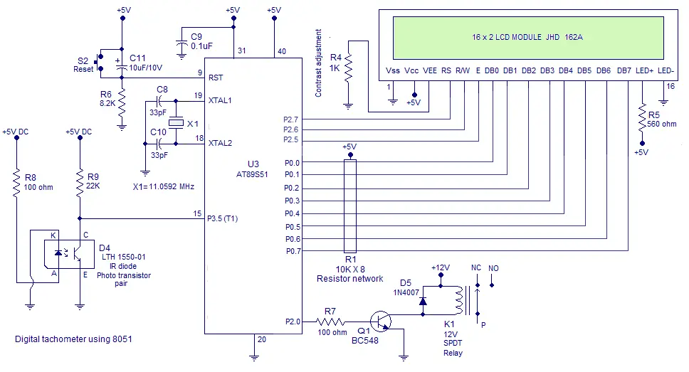
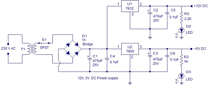
Power supply circuit.
A simple 12V, 5V/1A power supply circuit based on voltage regulator ICs 7805 and 7812 is given below.
Program for the LCD tachometer.
    RS EQU P2.7
    RW EQU P2.6
    E  EQU P2.5
    ORG 00H
MOV DPTR,#LUT
SETB P3.5
CLR P2.0
MAIN: MOV R6,#22D
      MOV TMOD,#01100001B
      MOV TL1,#00000000B
      MOV TH1,#00000000B
      SETB TR1
BACK: MOV TH0,#00000000B
      MOV TL0,#00000000B
      SETB TR0
HERE: JNB TF0,HERE
      CLR TR0
      CLR TF0
      DJNZ R6,BACK
      CLR TR1
      CLR TF0
      CLR TF1
      MOV A,TL1
      CJNE A,#75D,SKIP
SKIP: JC SKIP1
      SETB P2.0
SKIP1:JNC CONT
      CLR P2.0
CONT: CLR PSW.7
      MOV B,#100D
      DIV AB
      MOV R0,A
      MOV A,B
      MOV B,#10D
      DIV AB
      MOV R1,A
      MOV R2,B

      MOV A,R2
      MOV B,#4D
      MUL AB
      MOV B,#10D
      DIV AB
      MOV R4,B
      MOV R2,A
      MOV A,R1
      MOV B,#4D
      MUL AB
      ADD A,R2
      MOV B,#10D
      DIV AB
      MOV R5,B
      MOV R2,A
      MOV A,R0
      MOV B,#4D
      MUL AB
      ADD A,R2
      MOV B,#10D
      DIV AB
      MOV R6,B
      MOV R7,A


      ACALL DINT
      ACALL TEXT1
      ACALL LINE2
      ACALL TEXT2
      ACALL NUM

      LJMP MAIN


 DINT: ACALL CMD
    MOV A,#0FH
    ACALL CMD
    MOV A,#01H
    ACALL CMD
    MOV A,#06H
    ACALL CMD
    MOV A,#83H
    ACALL CMD
    MOV A,#3CH
    ACALL CMD
    RET

TEXT1: MOV A,#84D
    ACALL DISPLAY
    MOV A,#65D
    ACALL DISPLAY
    MOV A,#67D
    ACALL DISPLAY
    MOV A,#72D
    ACALL DISPLAY
    MOV A,#79D
    ACALL DISPLAY
    MOV A,#77D
    ACALL DISPLAY
    MOV A,#69D
    ACALL DISPLAY
    MOV A,#84D
    ACALL DISPLAY
    MOV A,#69D
    ACALL DISPLAY
    MOV A,#82D
    ACALL DISPLAY
    RET

TEXT2:MOV A,#82D
      ACALL DISPLAY
      MOV A,#80D
      ACALL DISPLAY
      MOV A,#77D
      ACALL DISPLAY
      MOV A,#32D
      ACALL DISPLAY
      RET

LINE2:MOV A,#0C0H
    ACALL CMD
    RET


NUM:MOV A,R7
    ACALL ASCII
    ACALL DISPLAY
    MOV A,R6
    ACALL ASCII
    ACALL DISPLAY
    MOV A,R5
    ACALL ASCII
    ACALL DISPLAY
    MOV A,R4
    ACALL ASCII
    ACALL DISPLAY
    MOV A,#0D
    ACALL ASCII
    ACALL DISPLAY
    RET


CMD: MOV P0,A
    CLR RS
    CLR RW
    SETB E
    CLR E
    ACALL DELAY
    RET

DISPLAY:MOV P0,A
    SETB RS
    CLR RW
    SETB E
    CLR E
    ACALL DELAY
    RET

DELAY: CLR EN
    CLR RS
    SETB RW
    MOV P0,#0FFh
    SETB E
    MOV A,P0
    JB ACC.7,DELAY
    CLR E
    CLR RW
    RET

ASCII: MOVC A,@A+DPTR
       RET

LUT: DB  48D
     DB  49D
     DB  50D
     DB  51D
     DB  52D
     DB  53D
     DB  54D
     DB  55D
     DB  56D
     DB  57D

    END
Program explanation.
The program actually counts the number of negative going pulses in 1.5 seconds and it is multiplied by 40 to get the number of revolutions per minute.
44 Comments
what is the purpose of relay in the lcd version and where is it connected to?
what is the purpose of relay?
how can we do it in proteus…
Can you Provide an lcd version of it please!
i have posted the LCD version below the main article. pls have a look.
Can this circuit be purchased on this site?
Thanks.
yes it will be available in our online store with in few days
I need briflly defintion &circut digram noncontact digital tachometer usin 8051 microcontroller .but not only three digit
could u show me how to design noncontact digital tachometer using 8051 microcontroller
Hi,
I’ve got this working and it’s really great but I would like to know if it is possible to have the 7 segment displays to display the speed constantly on rather than them to be flashing.
do you have layout of this project?
We are working on the layout part! Will be updated on this page.
Hey, Can you tell me how much space have you given between the LED & the phototransistor for the proper calibration of the Output.!!
Thank You.
they were place close together touching with some 1mm gap i think
I want to ask whether the mechanism in this project counts the pulses for 60 seconds and then display it (if so then how to configure 8051 to delay time for 60 sec and at the same time count the pulses in that duration?) or it measures the speed instantaneously and also displays instantaneously (sorry if the question seems to be silly i am at very beginning with learning microcontrollers)
please send me a program .hex file to my mail ID for “Digital
tachometer using 8051” please
If possible would u please furnish me with the PCB layout of the circuit of tachometer using 8051 given.
I’m looking forward to realize the circuit provided and therefore would be easier for me to move ahead with the project if the layout is available with you.
Thank you
did you get the things you asked for?
hi , i have a trouble with the timer.. i don’t really know whether my circuit works or not. my project is to connect this project to LCD 16×2..
i can send you my circuit and my code in .rar so can you help me?
thanks..
I have a problem in the optical pick up assembly. i am not getting the pulse at output of lm324. plz refer me how can i get the continuous pulse at the output or give me another method for this…
Aniket Rakshe
Mo. 9503305658
Email: aniket.rakshe71@gmail.com
This is for my study and teaching the 8051 program how to srite
Thanks a lot for the Originators.
What is the use of burner circuit of 8051 microcontroller in this device?
please reply.
Hae there,i want to make the tracometer but a few things are troubling me.namely:
-what programing language have you used to program the microcontroller
-about the dispaly,how do i know the terminals,i mean which is which
-Where do i buy Ic2
-can you give me an alternative proggram for an arduino board with respective connection?
-Programming language used is C-Assembly level language. You an use Keil to code, compile and test the program code.
-IC 2 is your 8051 series u-controller(micro) it is easily available in the market both online and offline. I bought a fresh u-controller from a local electrical components store for a $(without dumper).
-Read the datasheet that came with your display to learn which pin is what.
Which must to be the distance between the RED LIGHT and the Phototransistor? if I wish to send the light acroos a hole directly
For this setup and every other setup based on principle of reflection of light the IR LED and the photo-sensor are placed side-by-side at a distance of 2-3mm from each other facing the obstruction which is generally less than 10cm away from the tip of IR LED.
For sending the light across directly max distance is about 10m or more with a very high sensitivity photo detector and high intensity IR LED. But this distance varies according to the climatic conditions in the region and also other devices operating in the area. Military uses high grade IR sensors that are able to operate for distances of few 10Km to 100Km.
For project purpose of measurement a distance below 1meter is suitable, but higher distances are possible if sensors are properly calibrated. T.V & A.C remotes use IR sensors to operate. I have tested my T.V remote to operate properly from distance of 5m at the most, on a sunny day with average temperature of 303 Kelvin. You have to test and calibrate your sensors based on application.
I’d like to install a disk and to do a small hole in the disk (It is for get the speed in a small lathe).- The disk will be installed in the Lathe’s shaft and in the back the Red Light.- I wish to have an idea about the distance between the Photo- Transistor and the light.- The second thing is about the color of the Led (RED) is it in relation with the frequency of the Red Light?
Thank you for all.- I finished a course of 8051 and I wish to practice with the device in order to get experience in program it.- This information help spo much to people like us
can i use at89c51 instead of at89s51 ?..what the differences?…tq 🙂
yesterday I asked if you supplied this instrument in kit form with the shaft sensor as well can you let me know please on my e mail address bigabbs1@sky.com
Thanks
Bri
Plz. Can you feed me thw same circuit with high sensitivity .
I didn’t got How will you seperate a number in the count by dividing it
by 100,10 etc…
Can u explain me How.
nice project I like to try this I hav an ISP programmer kit but I dont hav serial port in my pc what can I do is there any alternative idea
Excellent job. Just one question. What you use to program the 8051? Any special interface cable? Thanks.
I use an In system programmer (ISP) module for programming the 8051. The user interface for programming the microcontroller comes with the ISP module. The module is connected to the PC through serial port. For creating hex file I use MIDE-51 compiler.
Hey, Can you tell me how much space have you given between the LED & the phototransistor for the proper calibration of the Output.!!
Thank You.
süpper good circuit
Dear Sir,
Kindly provide C code for better understanding.
Regards
Vinay Parmar
Baroda – Gujarat
India
ph:+91 9427352904
Hello Vinay,
We will try to bring up a “”C” code in near future.
both C code and assembly level program should be provided for these kind of interfacing… It really helps a lot.