Diode Clippers – A study of various Clipping Circuits
This article explains the working of different diode clipper circuits like Positive and Negative Diode Clippers, Biased Clipper circuit, and Combinational Clipper Circuit with the help of circuit diagrams and waveforms.
What is a clipping circuit?
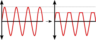
A clipping circuit or a clipper is a device used to ‘clip’ the input voltage to prevent it from attaining a value larger than a predefined one. As you can see in the picture below this device cuts off the positive or negative peak value of a cycle.
The basic components required for a clipping circuit are – an ideal diode and a resistor. In order to fix the clipping level to the desired amount, a dc battery must also be included. When the diode is forward biased, it acts as a closed switch, and when it is reverse biased, it acts as an open switch. Different levels of clipping can be obtained by varying the amount of voltage of the battery and also interchanging the positions of the diode and resistor.
Depending on the features of the diode, the positive or negative region of the input signal is “clipped” off and accordingly the diode clippers may be positive or negative clippers.
There are two general categories of clippers: series and parallel (or shunt). The series configuration is defined as one where a diode is in series with the load, while the shunt clipper has the diode in a branch parallel to the load.
1. Positive Clipper and Negative Clipper
Positive Diode Clipper
In a positive clipper, the positive half cycles of the input voltage will be removed. The circuit arrangements for a positive clipper are illustrated in the figure given below.

As shown in the figure, the diode is kept in series with the load. During the positive half cycle of the input waveform, the diode ‘D’ is reverse biased, which maintains the output voltage at 0 Volts. This causes the positive half cycle to be clipped off. During the negative half cycle of the input, the diode is forward biased and so the negative half cycle appears across the output.
In Figure (b), the diode is kept in parallel with the load. This is the diagram of a positive shunt clipper circuit. During the positive half cycle, the diode ‘D’ is forward biased and the diode acts as a closed switch. This causes the diode to conduct heavily. This causes the voltage drop across the diode or across the load resistance RL to be zero. Thus output voltage during the positive half cycles is zero, as shown in the output waveform. During the negative half cycles of the input signal voltage, the diode D is reverse biased and behaves as an open switch. Consequently, the entire input voltage appears across the diode or across the load resistance RL if R is much smaller than RL
Actually the circuit behaves as a voltage divider with an output voltage of [RL / R+ RL] Vmax = -Vmax when RL >> R
Negative Diode Clipper
The negative clipping circuit is almost the same as the positive clipping circuit, with only one difference. If the diode in figures (a) and (b) is reconnected with reversed polarity, the circuits will become for a negative series clipper and negative shunt clipper respectively. The negative series and negative shunt clippers are shown in figures (a) and (b) as given below.

In all the above discussions, the diode is considered to be the ideal one. In a practical diode, the breakdown voltage will exist (0.7 V for silicon and 0.3 V for Germanium). When this is taken into account, the output waveforms for positive and negative clippers will be of the shape shown in the figure below.

2. Biased Positive Clipper and Biased Negative Clipper
A biased clipper comes in handy when a small portion of positive or negative half cycles of the signal voltage is to be removed. When a small portion of the negative half cycle is to be removed, it is called a biased negative clipper. The circuit diagram and waveform is shown in the figure below.

TIn a biased clipper, when the input signal voltage is positive, the diode ‘D’ is reverse-biased. This causes it to act as an open-switch. Thus the entire positive half cycle appears across the load, as illustrated by output waveform [figure (a)]. When the input signal voltage is negative but does not exceed battery the voltage ‘V’, the diode ‘D’ remains reverse-biased and most of the input voltage appears across the output. When during the negative half cycle of input signal, the signal voltage becomes more than the battery voltage V, the diode D is forward biased and so conducts heavily. The output voltage is equal to ‘- V’ and stays at ‘- V’ as long as the magnitude of the input signal voltage is greater than the magnitude of the battery voltage, ‘V’. Thus a biased negative clipper removes input voltage when the input signal voltage becomes greater than the battery voltage. Clipping can be changed by reversing the battery and diode connections, as illustrated in figure (b).

Some of the other biased clipper circuits are given below in the figure. While drawing the wave-shape of the output basic principle discussed above are followed. The diode has been considered as an ideal one.

3. Combination Clipper
When a portion of both positive and negative of each half cycle of the input voltage is to be clipped (or removed), combination clipper is employed. The circuit for such a clipper is given in the figure below.

The action of the circuit is summarized below. For positive input voltage signal when input voltage exceeds battery voltage ‘+ V1‘ diode D1 conducts heavily while diode ‘D2‘ is reversed biased and so voltage ‘+ V1‘ appears across the output. This output voltage ‘+ V1‘ stays as long as. the input signal voltage exceeds ‘+ V1‘. On the other hand for the negative input voltage signal, the diode ‘D1‘ remains reverse biased and diode ‘D2‘ conducts heavily only when input voltage exceeds battery voltage ‘V2‘ in magnitude. Thus during the negative half cycle the output stays at ‘- V2‘ so long as the input signal voltage is greater than ‘-V2‘.
Drawbacks of Series and Shunt Diode Clippers
- In series clippers, when the diode is in ‘OFF’ position, there will be no transmission of the input signal to output. But in the case of high-frequency signals transmission occurs through diode capacitance which is undesirable. This is the drawback of using the diode as a series element in such clippers.
- In shunt clippers, when the diode is in the ‘off condition, transmission of input signal should take place to output. But in the case of high-frequency input signals, diode capacitance affects the circuit operation adversely and the signal gets attenuated (that is, it passes through diode capacitance to ground).
Applications of clipping circuits
- Used in FM transmitters to reduce noise
- To limit the voltage input to a device
- To modify an existing waveform to the desired output
Also, check this – https://www.circuitstoday.com/diode-clippers-applications
To gain more knowledge about various other Clipping circuits – say Clipping circuits using Transistors, Applications of Diode clippers etc. Follow the links below.
TAKE A LOOK : CLIPPING CIRCUITS
TAKE A LOOK : TRANSISTOR CLIPPING CIRCUITS
TAKE A LOOK : DIODE CLIPPERS – APPLICATIONS
TAKE A LOOK : DIODE CLAMPING CIRCUITS
84 Comments
transfer characteristics are also important which are missed in this explanation…
nyc article, thanks a lot
I have a doubt.In the first 3 example input signel is directly given to a cell. Can apply a input signel directly into a cell.please any one provide the answer.
can someone plz tell me how will practicall biased clipper work (where we have a dc source plus 0.7V of silicon diode itself also)?
U should emphasize more on ‘how it gets clipped or clamped’
My doubts r not cleared yet….
what is peak clipper
iiiiiiiiiiiiii lllllllllllllllllllllllllllllllllllllliiiiiiiiiiiiiiiiiiiiiiikkkkkkkkkkkkkkkkkeeeeeeeeeeeeee
thanks for give information. thank u once again.
It was helpful but more emphasis should be given on the working of biased clipper, like how do they actually work and what happens with the help of schematic diagrams… Otherwise a very helpful article
it was helpful…
designing of problem based on climper & clamper
where is slicer?
There are three more names of Clipper,one of them is known as “slicer”… !!!
Please tell that other two names of Clipper circuit!
very useful as its too easily presnted and can b understood very wellworth reading
i don’t think so… there is no explanation of any circuits..
still thanks
thanxxxx
Thanks… A nice attempt for the students like us…
Thank so much…
thanks a lot. but the output graph of (f) is wrong .. if you want to correct this check this out
http://www.electronics-tutorials.ws/diode/diode-clipping-circuits.html
thanks a lot because it was necessary for me .
nice wording and good explanation?but pics are too little>??
This is one of the best ways that solve the students problems …Thank You ..
thankyou very much.i never understood how the biased ones.thanks to you ,now i do.i am very grateful.
Thanks alot
thanks its helped me a lot
i,m still confuseeeedddddddd
where are the formulas ?
thnq…
information about other cliper circuits not given so i wasnt able t understand it well…plzzz can you provide me sufficent info 4 this..??
thank u a lot wil re visit
thanks a lot for your help
REALLY I APPRICIATE IT AFTER DEEPLY STUDY……….I HAD PROBLEM FOR ANALYSIS OF CLIPER CIRCUIT ,,,,,,BUT I HAVE NO PROBLRM NOW………………THANKS ALOT…..
very easy and good language and point to point answer……
i reallllllllllllllllllllllllllllllllllllllllllly like the
clipper in life
v.v.v.vnice explenation
why is resistor connected in series with load in series clipper
when the diode is forward biased current flow is high… so to protect the diodes from the heavy flow of current , resistors are used in series…
the whole explanation is very nice…………..
i have understood this very well now…..
simple and to the point explanation. wish my lecturer could read this prior to class.
it is very nice…….
i understd this very well…..
IZZA,
You are right, the biased negative clipper output wave form doesnt clipped off.
I think it will clipped on -(V+D)
v is the voltage source
and
D is the drop in diode
Get some Tips and Tricks in Clipping Circuits
TRICKS IN CLIPPING CIRCUITS
I think “Biased Negative Clipper” figure output waveform is wrong. ! let me know if it is my mistake. thanks anyway
Thanks for the inf.. In short all required data is given…
please explain combine diode circuit with Rquation solver by 3 steps which are given in Boylested Book….
Thanks a lot..Though information is very less but it is valuable to me
after read this article i get more confused…….?
any body can help me..?
I feel gud to read all this.
very nice artical
if some mathematical problem is included with explanation,it will be so helpful.But this makes me understand the clippers,thanks
am bouyant on dis topic
it is bs8 way to understand. Thank’s……………
this is good way to solve all the student problems.
Hi I am a physics department student, i have a question abuot last picture, if we turn the dc voltage supllies 180 degree, then how it would be the Vout signal
Good one!!!!!!!! .Helped me clear my doubt.
i want to know that when diode is in series with load and battery then why another level v or -v is introduced in output waveform
THAX A LOOOOOOOOOOOOOOOOOOOOOOOOOT I M MUCH SATISFIED AFTER READING ALL
thanks…………..
thanks for giving infomation.
I was so confused between series and shunt clippers,but now i think every thing is OK; thank u so much.
plz correct the biased -ve clipper o\p waveform…..
VYSAKH,PLEASE SEND ME NOTE OF CLIPPERS
derivation is not clear so make it clear
thank u for this,but iam still not solved it properly.
biased negative clipper output waveform is wrong plz correct it
@pallavi
please giv your e mail id, will sent complete note about biased clipper
I am still not getting the working of biased clipper
pls explain more abt clippers. explain shunt & series clippers in 2 versions. thats all THANK U 4 ur help.
i wanna design clipper n pspice plz give values of components… thanx alot……..
i’d problem in clippers but now i’ve resolved from it
Images are redrawn. Now they are clear and perfect. Thanks a lot to every one who commented.
thanks alot dude
really wonderful!!!!!!!!!!
but images are too small………
combination clipping information is less………
if diode is not ideal no diagrams are mentioned…..
Thanks a lot!!! Easy to understand.
If only the pics were a little bigger…
itz great nd easy to understand
images of series biased clipper are too small. nice description
really nice description… but images r too small..
@jeena— all the current will pass through the diode when forward bias leaving no voltage drop accros the resistor..too simple to understand…
thanks….got all that i wanted….wish the ckt diagrams were a little bigger….its not clear….
Hi you have to sufficiently amplify the signal before feeding to this clipping circuit if input is less than 600mV nothing will happen to the waveform as the diode cannot conduct.
the output cannot be greater than 600mv (1200mV pk – pk) so you have to amplify further to increase the waveform level.
what about the drop across R when shut clipper is considered. When will you tell the diode is forward biased if the drop across R is not known?
combination clipping information is too less and vague also diagram is not visible clearly
the image was way too small to be seen…