Description.
The circuit given here can be used for tossing head or tail. There are many games in which a tossing is required to start and this circuit can be used in all such instances.
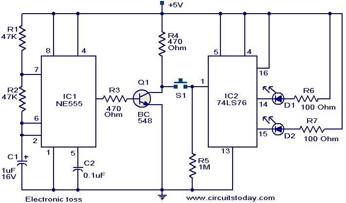
The circuit uses two ICs NE 555 timer (IC1) and 74LS76 dual JK flip flop (IC2).The IC 1 is wired as an astable multi vibrator operating at 10Hz.The output of IC1 is inverted by using the transistor Q1.The collector of Q1 is connected to the pin 1 of IC2 via the push button switch S1.The IC2 is wired in toggle mode. When push button S1 is pressed the output pins 14 and 15 of IC2 starts toggling in state. The LEDs connected to these pins also toggles (Since the frequency of toggling is 10Hz, we feel both LEDs glowing).When push button S1 is released either one of the LED remains ON indicating the head or tail.
Circuit diagram with Parts list.
Notes.
- The circuit can be powered from 5 V DC.
- Switch S1 is a push button switch.
- The ICs must be mounted on holders.
- The circuit can be assembled on a general purpose PCB.
22 Comments
Use IC 7473 instead of IC 7476.The out will come easily and better.
The basic problem I experienced with this circuit was instability and spurious clocking of the 7476 with the push button in its present position.
I found the input to the 7476 was acting like an aerial.
A practical modification to this circuit would be to move the push button switch to the output of the 555
This really does stabilise the input to the 7476 because the transistor, BC548 buffers the input to the 7476 with no spurious clocking at all.
project
i am doing this project,
i dont getting 5v battery…..
wt to do?
Avinash use 6 volt battery with 1no 1N4002 diode in series in the positive line it will become 5.3 volts, should be ok for the ICs operation.
Hey guyz,
what will be the cost to making this ckt?
Can it be use by multimedia
FINE CIRCUIT,,,,,Oh SO FINE!!!!
This is a Fun Circuit!!!
I WANT TO BUILD THIS CIRCUIT TODAY!!!
NICE CIRCUIT!!!!!!!!!!
Nice Circuit. Just 1 question.. Why do we need to invert the output from NE555? Wont NE555 provide a positive output?
Hi Arun sorry for the miss, pin no3 is output of IC.
From which terminal of NE555 R3 is taken??
it is 3rd terminal
Hi Bari To invert the pulse from NE555 IC. The input requirement for 74LS76 should be positive going to respond, the negative going pulse of IC 555 is inverted for 74LS76 to respond.
what is the role of BC548 in this electronic circuit?
its a vry usful & gud design…..on which i scored 10/10 in board exam
its a outstanding design…well,i want a ckt design of a “motion sensor”…
m not getting what i want i want a electronic toss circuit which uses only 1 IC 7404 a hex inverter
Тема ну просто пиздец.
Неужели ничего поактуальней не нашлось?