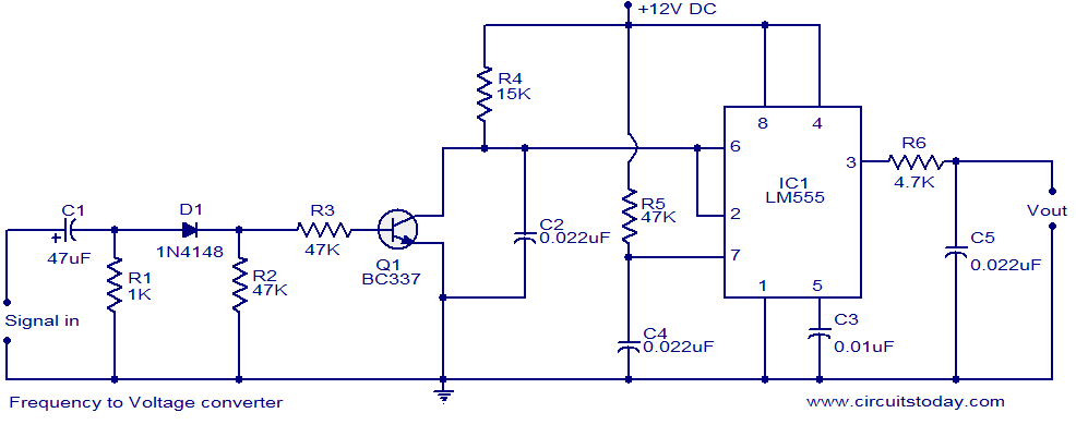
F to V Converter Circuit using LM555 Timer
Description.
Here is a very simple circuit diagram of a frequency to voltage (F to V) converter. Such a circuit finds numerous applications in projects like digital frequency meters, tachometers etc. The circuit is mainly based on a LM555 timer IC. The IC is wired in mono shot mode to convert the input frequency into a fixed pulse width, variable frequency PWM signal. Resistors R4 and capacitor C2 provides the necessary timing for the circuit. The transistor T1 forms a discharge path parallel to C2 which is necessary for re triggering the IC. Capacitor C1 acts as an input DC decoupler.
Circuit diagram.
Notes.
- The circuit can be assembled on a Vero board.
- Use 12V DC for powering the circuit.
- LM555 must be mounted on a holder.
- The output of the circuit is not a pure DC but a PWM waveform. Additional circuitry is required to convert this PWM waveform to pure DC.
CircuitsToday.com has introduced an online store to buy books that provide the basics and applications of 555 timer IC. There are 3 books in store. You can buy them after reading our reviews. Know more- 3 Great Books to Learn 555 Timer Circuits and Projects


26 Comments
please sir can you explain step by step the operation of the circuit.please
sir can please explain step by step how the circuit work.
thank you
will the circuit work for freq upto 200KHz ??
what is the operation of the circuit????
hi, even though i varied the range of frequency it producing only 5v. is this designed for producing 5v.then how to increase the output voltage?
REMOVE CAP C5 AND CHECK
Is it possible that you can tell me which are the timing C/R’s that establish the fixed pulse width timing and which are the ones that establish the overall time period? I am looking for a pulse width of about 1ms that can be pulsed over a period up to 1 second. Thank you in advance.
R5 and C4 determine the pulse width (multiply these to values together in farads and ohms and you will get the time constant in seconds i.e. 0.022/1000000 x 47 x 1000 = 0.001034 sec, about a milisecond) and the overall time period is determined by the input signal at IC1 pins 6 and 2.
R5 and C4 lead to nowhere and can be omitted. C1 and R1 define the fixed pulse width, but only for square wave signal with constant amplitude. R2 and R3 can be neglected while R1 is much smaller than R2 and R3. Otherwise a paralel combination of R1, R2 and R3 with some influence of D1 and Q1 must be considered. R4 and C2 establish the overall time period or in other words the f/V ratio. The IC1 act only as comparator with hysteresis. R6 and C5 are that additional circuitry which was mentioned in the circuit description, but work only when R6 C5 time constant is longer than period of the input signal.
i want explanation & operation for this circuit
hello, i want to ask u how dose the out put look like? after conecting the circuit we couldent find pure wave for out put!
what is the output for this circuit that should appear in the oscilloscope device ??
This circuit is to decode contents of a modulated FM signal. This requires energy to do the job. hence it can not be used for your application. Instead use the telephone line voltage to charge the battery.
HI, i am refering this circuit for my project( charging battery using FM radio )
can I give FM frequency range to this circuits. .?
pls help me this is my first project. . .
hellow,
May I know the formula of conversion and its range. (F to V)
thanks
Hi Vinod you can use LM331 for this application which is most suited
http://www.national.com/ds/LM/LM231.pdf
i want the f to v converter in the range 20khz to 40 khz can i get this with some change in component value
1.what is the magnitude of input signal
2.can i convert 50Hertz frequency of AC supply into voltage
if yes at what voltage it works
Oh, one more:
– how can I get the inverted output?
Thanks again.
This circuit looks like it could work for my project: speed-sensitive dimming for my LED bicycle lights. I’m using a BuckPuck 3023 LED driver, which can accept a 0-5v inverse control voltage (0v=max, 5v=off). A few questions:
– can I power the 555 with 5v? (the ref. voltage supplied by the BuckPuck)
– I think I want about 3.5v at 0 hz, and 0v at 150hz….what R and/or C values would need to be adjusted to get that?
– can I use a magnetic reed switch to sense wheel rotation?
Sorry if these are dumb questions….I don’t know much about electronics. Thanks.
this ckt is titled as voltage to frequency one. but at the start of ckt description it is written HERE IS A VERY SIMPLE CIRCUIT OF FREQ TO VOLTAGE [ F TO V ] CONVERTER.PL SEND ITS CORRECTION
That was a typing error from my part.
The circuit is a frequency to Voltage converter
Sorry for the in convenience.
thanks for pointing the error.
tell me how to input the signal? and at what frequency?thanks dear