Description.
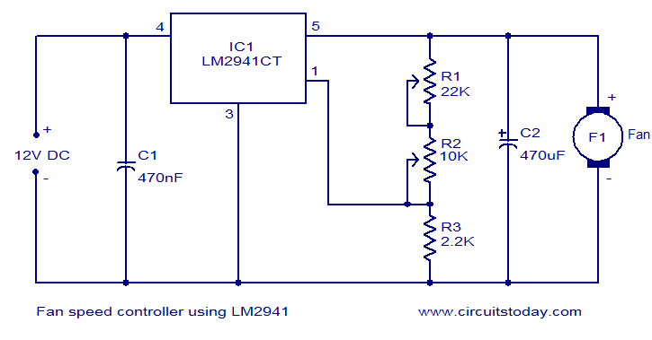
Many electronic circuits related to fan speed controlling have been published here and this one is just another approach. The circuit diagram shown here is of 12V DC fan speed controller using the IC LM2941CT which is a low drop out 1A voltage regulator. The IC has a dropout voltage as low as 0.5 and has also many useful features like power supply reverse protection, thermal protection, short circuit protection etc. The maximum output current the IC can source is 1A.
The 12V DC supply is connected between the Vin (pin4) and ground (pin3) of the IC. The load, which is the fan, is connected across the Vout (pin5) and ground (pin3) of the IC. The network comprising of potentiometers R1, R2 and resistor determines adjust current (Iadj) of the IC. By varying the Iadj using the POT R2 we can adjust the output voltage of the IC and hence the fan speed.
Circuit diagram.
Notes.
- The circuit can be powered from 12V DC.
- The maximum possible load current is 1A.
- A heat sink is recommended for the IC.
- POT R1 can be used to adjust the minimum fan speed.
- POT R2 can be used to adjust the fan speed.


29 Comments
is it automatic control or not
Hello! Can please be doing my work all for me? Thank you!
can u send the pdf for this project for me?
sir,will u please send the explanation for this project to me(muthu.mahes9@gmail.com).Becaz i will try to made the project in our college.
With rage of fan is use in fan speed controller using LM2941CT
i made this project sir will u plz tell me where i connect the 2 pin of ic………..????? or leave it
It is only for shutdown need not be used.
sir i want simulation report of this project.. so plz send me the report at email id… gaurav.hunk2009@gmail.com
i hve to give the presentation in my class i need more information so can you plzz send it to me
I always enjoy your site.
i am trying to make the circuit to my college project. How to make the project and please send the layout the circuit and explanation of the circuit. . . .
Please to help me for to complete the project. . .
In interfacing 7 sdgment 8051,there are some one are earthed.what this exactly do?
hi, i am trying to build a 12v 50A variable speed controller for my car. can you tell me what i need to replace to get that results. the fan is pulsed with a square impulse from the computer(ecu)
Thats simple… but how do we change the pot electronically?
thank you sir 🙂
Hi Gerald use thick copper (10 to 20 mm) strips used as link in high current cable links or thick aluminium bars. donot use without heat sink.
is it ok not to put a heat sink for the IC?? In case there is no heat sink available, what can I can use as an alternative?
Hello guys, I am trying to make this circuit as my college project. I got the required output on breadboard but fail to get output on pcb when layout done on eagle software; I guess I dont know to use the eagle software. So can any1 please mail me the layout of this circuit on ANKIL19@hotmail.com ? It will be of tremendous help. thank you
Hi Hammed you can use this circuit for 220volt AC 50Hz fans
https://www.circuitstoday.com/modified-lamp-dimmer-circuit
please can i get a circuit diagram for a 220v fan controller
Hi Soji it is for controlling the speed of 12 volt DC Motor.
sir in this experiment( fan speed controller using the IC LM2941CT) ,,sir which type of motor is to be used whether a 12 volt motor…or something else
What is the lowest practical RPM delivered by this controller?
the design of circuit easy.
low cost of this circuit . very popular one
Hi Probir the maximum current through R1 & R2 cannot be more than 6mA. Hence any potentiometer available in the market can be used.(Miniature pots are 100mw std ones are 250mw)
what should be the wattage ratings of resistors R1 & R2.
good job
i have a guestion
what is the way that i can control any other thing with high current
this is the best site fr circuits