Undoubtedly, frequency is one of the fundamental parameters for any electronic equipment. Frequency specifies the rate of oscillatory movements and vibrations. In electrical and electronics, frequency measures the rate of oscillatory movement of current flowing through a circuit. The international unit of frequency is Hertz that equals 1 cycle per second. Want to know how to measure these intricate parameters? This article deals with a frequency counter, test equipment that measures frequency. You will also get to know how you can use ARDUINO to make one for yourself by the end of the article. So let’s get started, shall we?
What is the Frequency?
In simplest terms, frequency is the rate at which something repeats itself. When we talk about electric current, it means the rate at which the sine wave repeats or completes a cycle. The power line frequency is usually either 50 Hz or 60 Hz,
What is Frequency Counter?
A frequency counter is a test instrument that measures frequency accurately. You can find its application in many radio frequency (RF), to measure the frequency of repetitive signals. These days, digital frequecy counters ahve made their ways to various circuitry.
The basic working principle of a frequency counter is that it counts the number of time signal passes a trigger point-mostly a voltage trigger point in a particular period of time.
The trigger points can be set to the desired value, if not, it is usually a zero-crossing point. For example, if you want to count the number of signals, and you have set a time point at second, then the counter will count the number of times the signal crosses the trigger point. If it crosses 50 times, you can say that the frequency of the signal is 50 cycles per second or 50 Hz.
Applications of Frequency Counter
The frequency counter finds application in various instruments, that are dependant on the frequency. The frequency, however, has to be a steady one, to get accurate results. These are used to measure frequency in the transmitter carrier, the oscillator in the circuit, analog, and digital signals, etc. In short, you can use the frequency counter whenever there is a requirement for you to measure the frequency of a repetitive signal.
Frequency Counter Using Arduino (up to 40KHz).
This frequency counter using Arduino is based on the UNO version and can count up to 40KHz. Components used for the project is listed below:
List of Components
- 16×2 LCD display
- Arduino IC
- 5V Voltage Source
- 10K Ohm Resistor-1 Nos.
- 560 Ohm Resistor-1 Nos.
- LED
A 16×2 LCD display is used for displaying the frequency count. The circuit has minimum external components and directly counts the frequency. Any way the amplitude of the input frequency must not be greater than 5V. If you want to measure signals over than 5V, additional limiting circuits have to be added and i will show it some other time. Now just do it with 5V signals.
The frequency to be counted is connected to digital pin 12 of the Arduino. pulseIn() function is used here for counting the frequency connected to pin 12. pulseIn() function counts the number of pulses (HIGH or LOW) coming to a particular pin of the Arduino. The general syntax of this function is pulseIn(pin, value, time) where the pin is the name of the pin, the value is either HIGH or LOW and time is the time for which the function to wait for a pulse. The function returns zero if there is no valid pulse within the specified time. The pulseIn() function can count pulses with a time period ranging from 10 μS to 3 minutes. A circuit diagram of the frequency counter using Arduino is given below.
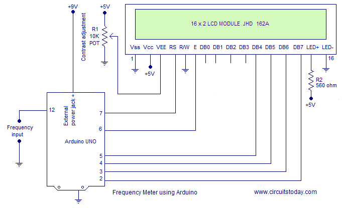
Potentimeter R1 is used to adjust the contrast of the LCD screen. Resistor R2 limits the current through the back light LED.
In the program, the high time and low time of the input signal are measured using separate pulseIn() functions. Then the high and low times are added together to get the total time period of the signal. Frequency is just 1/time period in seconds. The pulseIn() function returns the time period in microseconds. The total time period in microseconds first divided by 1000. Then 1000 is divided by the result to get the frequency in hertz. The program of the frequency counter using Arduino is shown below.
Program
#include <LiquidCrystal.h>
int input=12;

int high_time;
int low_time;
float time_period;
float frequency;
LiquidCrystal lcd(7, 6, 5, 4, 3, 2);
void setup()
{
pinMode(input,INPUT);
lcd.begin(16, 2);
}
void loop()
{
lcd.clear();
lcd.setCursor(0,0);
lcd.print("Frequency Meter");

high_time=pulseIn(input,HIGH);
low_time=pulseIn(input,LOW);


time_period=high_time+low_time;
time_period=time_period/1000;
frequency=1000/time_period;
lcd.setCursor(0,1);
lcd.print(frequency);
lcd.print(" Hz");
delay(500);
}
Circuit Application
The circuit can be powered through the 9V external power jack of the Arduino. 5V DC required at some parts of the circuit can be tapped from the built-in 5V regulator of the Arduino itself. This is actually a simple counter circuit using Arduino. We can modify this circuit for other applications like tachometer, intrusion counter, etc.
Conclusion
Frequency counters are one of the essential test instruments with a wide range of applications. You can easily create one using Arduino with the program and circuit, we have discussed in this project-based article. You can always experiment with the circuit and build your own frequency counter Hope this article clears your basics about frequency and frequency counters.
18 Comments
input – speed of two stepper motor
output-digital frequency pulses which has to be further given to a driver ckt
hi please help me for the coding
input should be speed of the two stepper motor that has to be converted into corresponding digital frequency pulses using arduino.
the output frequency pulse has been further given to a driver.
Hello,
I am doing project of remote monitoring and control of a generator. I am facing some difficulty in some part of the program. Could you please guide me? i can provide you my code and circuit simulation .
thank you
This is good but what about circuitry to limit the peak voltage of the input frequency and also to deal with a floating input – e.g. swinging between, say, -10v and +10v. My inclination is to use an op-amp buffer with a 3v9 zener between the output and ground (plus a load resistor, of course). It could also be used to shape sine and other non-sq waves into square waves.
What it the lower limit at which the counter can act?
i’m trying to measure audio frequency. is this coding able to do so?
Whether can I apply the sine signal to the input pin
hello sir
if I change the frequency of the input signal simultaneously whether it is showing the exact output frequency as same as input.
send me the screenshots of this program simulation in proteus . I am not getting the output
Whether can I apply the sine signal to the input pin
Dear sir
My project have to make arduino board for check freq counter 10 – 60 MHz
connector is BNC
I have old freq counter, my boss want to replace it to arduino.
Please see in the picture
http://img.coolz-server.com/2015-02-24_09-05-06_0.976285.jpg
http://img.coolz-server.com/img/2015-02-24/09-05-06_0.981947.jpg
Could you advise to me
Thank you
@champasit – Please wire up the circuit and use code we have given. We have tested this in our lab!
jojo what input you r applying to the aurdino
pulse input? ?
Could you please tell what software you are using for drawing the circuits.
PCB123