Humidity sensor using 8051 (Hygrometer)
This project is about a simple humidity sensor based on 8051 microcontroller. Humidity sensor is also called hygrometer. This circuit can sense relative humidity (RH) from 20% to 95% at an accuracy of 5%. The humidity information is displayed on a 16×2 LCD display. A relay is also provided which is set to be active when the humidity crosses a certain trip point. The circuit is mains operated and it is very easy to install. DHT11 is the humidity sensor used here. The details and working of the DHT11 humidity sensor is given below.
DHT11 humidity sensor.

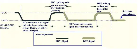
DHT11 is a low cost humidity cum temperature sensor which has a digital output. Capacitive method is used for sensing the humidity and a thermistor is used for measuring the temperature. The sensor can sense relative humidity from 20% to 95% at a resolution of 5%. Temperature measurement is up to 50°C at a resolution of 2°C. The communication with the microcontroller is through a single wire. The basic communication scheme is given in the image below.
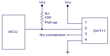
The to and fro communication with DHT11 sensor is very easy. Pin 2 of the DHT11 is connected to the port pin of the micrcontroller. The connection scheme is shown in the image below. The data pin (pin2) of the DHT11 requires an external 10K pull-up resistor.
The communication protocol is explained as follows. The MCU (microcontroller unit) first sends a low signal of width 18mS to the DHT11. After this signal, the MCU pulls up the communication line and waits for the response from DHT11. It make take up to 2. to 40uS. Then the DHT11 pulls down the communication line and keeps it low for 80uS. Then DHT11 pulls up the line and keeps it high for 80uS. Then the DHT pulls down the line for 50uS and the next high pulse will be the first bit of the data. The data is send in bursts of 8 bits. Each high pulse of the burst indicates a data signal. The 50uS low signals between the data bits are just spacers. The logic of the data bit is identified by measuring the width of it. A 26 to 28uS wide pulse indicates a “LOW” and 70uS wide pulse indicates a “HIGH”. In simple words, an pulse narrower than 50uS can be taken as a “LOW” and wider than 50us can be taken as a “HIGH”. The first 8 bits of the data burst represents the integral value of the relative humidity, second 8 bits represent the decimal value of the relative humidity, third 8 bits represent the integral value of the temperature data, and the last 8 bits represent the decimal value of the temperature data, For DHT11 the decimal values are always zero and we are measuring the relative humidity only in this project. So we need to just concern about the first 8 bits of data, that is the integral part of the relative humidity data. Circuit diagram of the humidity sensor is shown in the image below.
Circuit diagram.
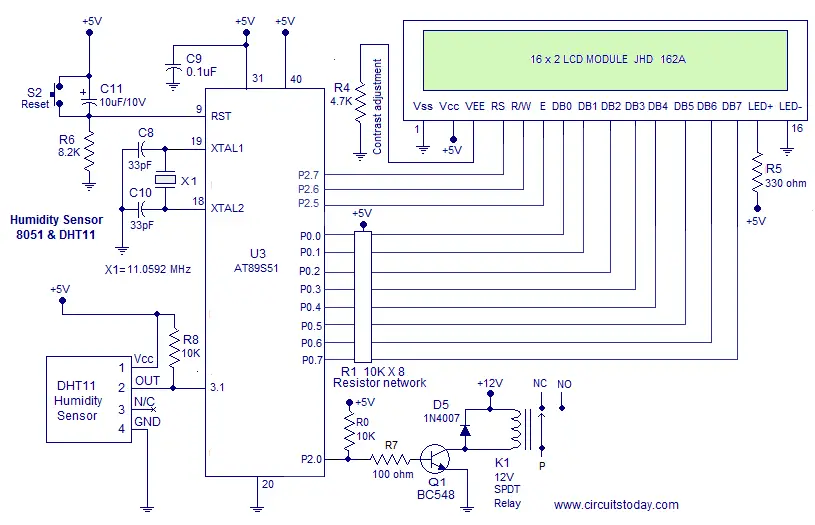
The humidity sensor DHT11 is connected to P3.1 of the 8051 microcontroller. R8 pulls up the communication line between DHT11 and 8051. The relay is driven using P2.0 of the microcontroller. Transistor Q1 switches the relay. R0 is a pull up resistor and R7 limits the base current of Q1. D5 is just a free-wheeling diode. Data lines of the LCD display is interfaced to Port 0 of the microcontroller. Control lines RS, R/E and E are connected to P2.7, P2.6 and P2.5 pins of the microcontroller respectively. R4 sets the contrast of the display. R5 limits the current through the back light LED. C9 is a by-pass capacitor. C8, C10 and X1 are associated with the clock circuitry. C11, R6 and S2 forms the reset circuit.
Program.
RS EQU P2.7
RW EQU P2.6
E  EQU P2.5
ORG 000H
MOV DPTR,#LUT
SETB P3.5
CLR P2.0
MOV TMOD,#00100001B
MOV TL1,#00D
ACALL DINT
ACALL TEXT1
MAIN: MOV R1,#8D
      SETB P3.5
      CLR P3.5
      ACALL DELAY1
      SETB P3.5
HERE:JB P3.5,HERE
HERE1:JNB P3.5,HERE1
HERE2:JB P3.5,HERE2
LOOP:JNB P3.5,LOOP
     RL A
     MOV R0,A
     SETB TR1
HERE4:JB P3.5,HERE4
      CLR TR1
      MOV A,TL1
      SUBB A,#50D
      MOV A,R0
      JB PSW.7, NEXT
      SETB ACC.0
      SJMP ESC
NEXT:CLR ACC.0
ESC: MOV TL1,#00D
     CLR PSW.7
     DJNZ R1,LOOP
     ACALL DINT
     ACALL TEXT1
     ACALL LINE2
     ACALL TEXT2
     ACALL HMDTY
     ACALL CHECK
     ACALL DELAY2
     LJMP MAIN


DELAY1: MOV TH0,#0B9H
        MOV TL0,#0B0H
        SETB TR0
HERE5: JNB TF0,HERE5
       CLR TR0
       CLR TF0
       RET

DELAY2:MOV R1,#112D
  BACK:ACALL DELAY1
       DJNZ R1,BACK
       RET

 CHECK:MOV A,R0
       MOV B,#65D
       SUBB A,B
       JB PSW.7,NEXT1
       ACALL TEXT3
       SETB P2.0
       SJMP ESC1
  NEXT1:ACALL TEXT4
        CLR P2.0
  ESC1:CLR PSW.7
       RET

 CMD: MOV P0,A
    CLR RS
    CLR RW
    SETB E
    CLR E
    ACALL DELAY
    RET

DISPLAY:MOV P0,A
    SETB RS
    CLR RW
    SETB E
    CLR E
    ACALL DELAY
    RET

HMDTY:MOV A,R0
      MOV B,#10D
      DIV AB
      MOV R2,B
      MOV B,#10D
      DIV AB
      ACALL ASCII
      ACALL DISPLAY
      MOV A,B
      ACALL ASCII
      ACALL DISPLAY
      MOV A,R2
      ACALL ASCII
      ACALL DISPLAY
      MOV A,#"%"
      ACALL DISPLAY
      RET


TEXT1: MOV A,#"H"
       ACALL DISPLAY
       MOV A,#"y"
       ACALL DISPLAY
       MOV A,#"g"
       ACALL DISPLAY
       MOV A,#"r"
       ACALL DISPLAY
       MOV A,#"o"
       ACALL DISPLAY
       MOV A,#"m"
       ACALL DISPLAY
       MOV A,#"e"
       ACALL DISPLAY
       MOV A,#"t"
       ACALL DISPLAY
       MOV A,#"e"
       ACALL DISPLAY
       MOV A,#"r"
       ACALL DISPLAY
       RET

TEXT2: MOV A,#"R"
       ACALL DISPLAY
       MOV A,#"H"
       ACALL DISPLAY
       MOV A,#" "
       ACALL DISPLAY
       MOV A,#"="
       ACALL DISPLAY
       MOV A,#" "
       ACALL DISPLAY
       RET
 TEXT3: MOV A,#" "
       ACALL DISPLAY
       MOV A,#" "
       ACALL DISPLAY
       MOV A,#"O"
       ACALL DISPLAY
       MOV A,#"N"
       ACALL DISPLAY
       RET

 TEXT4:MOV A,#" "
       ACALL DISPLAY
       MOV A,#"O"
       ACALL DISPLAY
       MOV A,#"F"
       ACALL DISPLAY
       MOV A,#"F"
       ACALL DISPLAY
       RET

 DINT:MOV A,#0CH
    ACALL CMD
    MOV A,#01H
    ACALL CMD
    MOV A,#06H
    ACALL CMD
    MOV A,#83H
    ACALL CMD
    MOV A,#3CH
    ACALL CMD
    RET

LINE2:MOV A,#0C0H
      ACALL CMD
      RET


DELAY: CLR E
    CLR RS
    SETB RW
    MOV P0,#0FFH
    SETB E
    MOV A,P0
    JB ACC.7,DELAY
    CLR E
    CLR RW
    RET

ASCII: MOVC A,@A+DPTR
       RET

LUT: DB  48D
     DB  49D
     DB  50D
     DB  51D
     DB  52D
     DB  53D
     DB  54D
     DB  55D
     DB  56D
     DB  57D
    END
Related Projects
Automatic Plant Watering System using 8051 – is an interesting and useful project for implementing in your home and feilds. The project makes use of YL69 moisture sensor and 8051 micro controller to complete the system. Soil moisture is measured with the help of YL69 sensor and based on the measured mositure level a motor is turned ON/OFF with the help of 8051.
About the program.
The communication protocol with the sensor and the microcontroller is already explained. Data out pin of the DHT11 is connected to P3.5 of the microcontroller. At the start of the MAIN loop, P3.5 is held high. Then it is made low and an 18mS delay routine (DELAY1) is called. Then P3.5 is made high. This forms the first 18mS wide start signal for the DHT11. Now the communication line is high and the microcontroller polls the status of this line and waits there until it is low. It becomes low when the DHT11 sends back the response signal. Then the microcontroller waits for the second response signal which is a high signal. When this high signal is received the microcontroller waits for the next low signal and after this low signal, data transmission starts.
I have already mentioned that, each data bit is represented by a high signal and the width of it determines the logic. So when ever the microcontroller receives a data pulse, Timer1 is started and the program waits there until the data pulse vanishes. Then the timer is stopped. Now the TL1 ie Timer1 low register contains the width of the data pulse. Then the width is compared with 50 by substracting 50 from the TL1 count. If carry flag (PSW.7) is set it means that the width is less than 50uS and if carry flag is not set it means that the width is higher than 50uS.
If width is less than 50uS it indicates a low signal and ACC.0 is cleared. If the width is higher than 50uS it indicates a high signal and ACC.0 is set.Then TL1 register and PSW.7 bit are cleared. Then the LOOP is iterated 8 times and accumulator is rotated left during the begining of each iteration. The rotate left (RL) instruction is used beacause during each iteration you updates ACC.0 only and you have to save that bit before the next update.This is achieved by shifting it to left each time.
The last update of ACC.0 doesnot require a position shift because it is in the right place it is supposed to be.That is the reason behind placing the RL A instruction at the begining of the LOOP. After the 8 th iteration the LOOP is exited without rotating the accumulator. Now the content of the accumulator is equal to the integral value of the current relative humidity in percentage.
Then subroutine DINT is called for initializing the display.Then subroutine TEXT1 is called which displays “Hygrometer”. Then subroutine LINE2 is called for shifting the cursor to 2nd line. Then subroutine HMDTY is called for displaying the humidity value in percentage.Then subroutine CHECK is called for checking whether the humidity value is above or below 65%. If humidity is above 65%, relay is activated and else the relay is deactivated. The the 2S delay subroutine DELAY2 is called. 2 second delay is given because you can take radings from the DHT11 once in every 2 seconds only.This also makes the display stable. Then the program jumps to MAIN label and the entire process is repeated.
8 Comments
What is the change in program code if I want to interface LCD at port 1.
Please answer!!
Good work. thanks. how can i make both humidity and temperature to display on the same LCD using 89c51 above.
I’ve one doubt : Humidity sensor using 8051 clockwise direction
WHAT ALL COMPONENTS ARE REQUIRED?
1. In ckt u shown that sensor is connected to P3.1 which is TX of mcu and in program u are explaining that sensor is connected to P3.5, so will u explain.
2. If sensor is connected to TX (P3.1) of MCU then how MCU will recieve data from sensor.
I was looking just something like this !!!! Thank you !!! It helps a lot.
i am trying to do the same project but instead of lcd i am trying to turn on led , if temperature goes above particular range then led 2 turns on & led1 turns off vice versa i have written a program but its not working as expected can you please help me in this
#include
#include
sbit LTdata = P2^0;
sbit led = P2^1;
sbit led2 = P2^2;
void delay1();
void delay2();
void delay3();
int getdata();
void startsignal();
unsigned int transferread(unsigned int );
unsigned int a,b;
void main ()
{
unsigned int value1,value2,value3,value4,value5;
void startsignal();
value1= getdata();
value2= getdata();
value3 = getdata();
a=value3;
value4= getdata();
value5= getdata();
transferread (a);
while (1)
{
void startsignal();
value1= getdata();
value2= getdata();
value3 = getdata();
b=value3;
value4= getdata();
value5= getdata();
}
}
unsigned int transferread(unsigned int i)
{
if ( i >b+10)
{
led=1;
led2=0;
}
else
{
led =0;
led2=1;
}
return 0;
}
void startsignal()
{
LTdata = 0;
delay1 ();
LTdata = 1;
delay2 ();
}
void delay1()
{
TMOD=0x10;
TL1=0xe8;
TH1=0xff ;
TR0=1;
while(TF1==0);
TR1=0;
TF1=0;
}
void delay2()
{
TMOD=0x10;
TL1=0xe4;
TH1=0xff ;
TR1=1;
while(TF1==0);
TR1=0;
TF1=0;
}
void delay3()
{
TMOD=0x10;
TL1=0xdb;
TH1=0xff ;
TR1=1;
while(TF1==0);
TR1=0;
TF1=0;
}
int getdata()
{
unsigned int num = 0,j;
for (j=0; j<8; j++)
{
while(!LTdata);
delay3();
if(LTdata)
num |= 1<<(7-j) ;
while(LTdata);
}
return num;
}
helpful