Instrumentation amplifier using opamp
Instrumentation amplifier is a kind of differential amplifier with additional input buffer stages. The addition of input buffer stages makes it easy to match (impedance matching) the amplifier with the preceding stage. Instrumentation are commonly used in industrial test and measurement application. The instrumentation amplifier also has some useful features like low offset voltage, high CMRR (Common mode rejection ratio), high input resistance, high gain etc. The circuit diagram of a typical instrumentation amplifier using opamp is shown below.
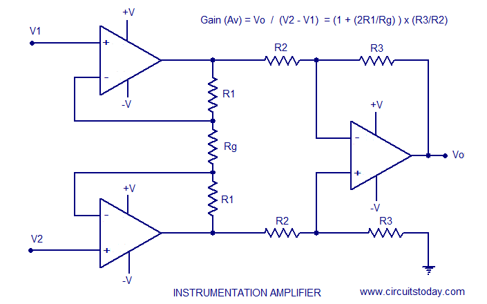
A circuit providing an output based on the difference between two inputs (times a scale factor) is given in the above figure. In the circuit diagram, opamps labelled A1 and A2 are the input buffers. Anyway the gain of these buffer stages are not unity because of the presence of R1 and Rg. Op amp labelled A3 is wired as a standard differential amplifier. R3 connected from the output of A3 to its non inverting input is the feedback resistor. R2 is the input resistor. The voltage gain of the instrumentation amplifier can be expressed by using the equation below.
Voltage gain (Av) = Vo/(V2-V1) = (1 + 2R1/Rg ) x R3/R2
If need a setup for varying the gain, replace Rg with a suitable potentiometer. Instrumentation amplifiers are generally used in situations where high sensitivity, accuracy and stability are required. Instrumentation amplifiers can be also made using two opamps, but they are rarely used and the common practice is to make it using three opamps like what is shown here. The only advantages of making an instrumentation amplifier using 2 opamps are low cost and improved CMRR.
A high gain accuracy can be achieved by using precision metal film resistors for all the resistances. Because of large negative feedback employed, the amplifier has good linearity, typically about 0.01% for a gain less than 10. The output impedance is also low, being in the range of milli-ohms. The input bias current of the instrumentation amplifier is determined by the op-amps A1 and A2.
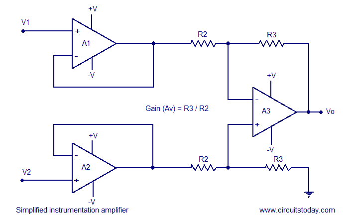
A simplified instrumentation amplifier design is shown below. Here the resistances labelled R1 are shorted and Rg is removed. This results in a full series negative feedback path and the gain of A1 and A2 will be unity. The removal of R1 and Rg simplifies the equation to Av = R3/R2.
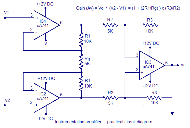
Practical instrumentation amplifier using opamp.
A practical instrumentation amplifier circuit designed based on uA 741 op amp is shown below. The amplifier operates from +/-12V DC and has a gain 10.If you need a variable gain, then replace Rg with a 5K POT. Instead of using uA741 you can use any opamp but the power supply voltage must be changed according to the op amp. A single LM324 op amp Ic is a good choice. Out of the four opamps inside the LM324, three can be used for IC1, IC2, IC3 and the remaining one can be left alone. This reduces the PCB size a lot and makes the circuit compact. Supply voltage for LM324 can be up to +/-16V DC.
An instrumentation amplifier is a differential amplifier optimized for high input impedance and high CMRR. An instrumentation amplifier is typically used in applications in which a small differential voltage and a large common mode voltage are the inputs.
11 Comments
Hiiiii my self shubham pandey that was so important information that i need it if u can then try to keep the practicle knowledge means with whole connecion what tto be get at the output when any input is ggiven ok thank you
can you suggest me instrumentation aplifier with high zin as much as 1000 megaom. gain may be unity.
sanjay agarawal
——————–
why gain is always described in decibel?
http://lmgtfy.com/?q=why+use+decibel+in+gain
What is the purpose of resister Rg in instrumentation amplifier?
IT IS GAIN ADJUSTMENT.
BY-THE WAY, WHAT YOU DO WITH I.A.
SANJAY AGARWEAL