In this guide, we’re learning how to interface LCD to Arduino and display text characters on LCD screen. We’re interfacing 16×2 LCD to Arduino as a demonstration with circuit and code. Let’s begin.
A Liquid Crystal Display commonly abbreviated as LCD is basically a display unit built using Liquid Crystal technology. When we build real life/real world electronics based projects, we need a medium/device to display output values and messages. The most basic form of electronic display available is 7 Segment display – which has its own limitations. The next best available option is Liquid Crystal Displays which comes in different size specifications. Out of all available LCD modules in market, the most commonly used one is 16×2 LCD Module which can display 32 ASCII characters in 2 lines (16 characters in 1 line). Other commonly used LCD displays are 20×4 Character LCD, Nokia 5110 LCD module, 128×64 Graphical LCD Display and 2.4 inch TFT Touch screen LCD display.
In this article, we are going to learn how to interface lcd to arduino with 2 examples – one being interfacing a 16×2 LCD module to Arduino and the other being interfacing a 20×4 LCD module to Arduino.
Interfacing 16×2 LCD to Arduino uno
LCD modules form a very important part in many arduino based embedded system designs. So the knowledge on interfacing LCD module to arduino is very essential in designing embedded systems. This section of the article is about interfacing an Arduino to 16×2 LCD. JHD162A is the LCD module used here. JHD162A is a 16×2 LCD module based on the HD44780 driver from Hitachi. The JHD162A has 16 pins and can be operated in 4-bit mode (using only 4 data lines) or 8-bit mode (using all 8 data lines). Here we are using the LCD module in 4-bit mode. First, I will show you how to display a plain text messages on the LCD module using arduino and then I have designed a useful project using LCD and arduino – a digital thermometer. Before going in to the details of the project, let’s have a look at the JHD162A LCD module.
16×2 LCD Module Pin Out Diagram
The JHD162A lcd module has 16 pins and can be operated in 4-bit mode or 8-bit mode. Here we are using the LCD module in 4-bit mode. Before going in to the details of the project, let’s have a look at the JHD162A LCD module.The schematic of a JHD162A LCD pin diagram is given below.

Pin1(Vss):Ground pin of the LCD module.
Pin2(Vcc): Power to LCD module (+5V supply is given to this pin)
Pin3(VEE):Contrast adjustment pin. This is done by connecting the ends of a 10K potentimeter to +5V and ground and then connecting the slider pin to the VEE pin. The voltage at the VEE pin defines the contrast. The normal setting is between 0.4 and 0.9V.
Pin4(RS):Register select pin.The JHD162A has two registers namely command register and data register. Logic HIGH at RS pin selects data register and logic LOW at RS pin selects command register. If we make the RS pin HIGH and feed an input to the data lines (DB0 to DB7), this input will be treated as data to display on LCD screen. If we make the RS pin LOW and feed an input to the data lines, then this will be treated as a command ( a command to be written to LCD controller – like positioning cursor or clear screen or scroll).
Pin5(R/W): Read/Write modes. This pin is used for selecting between read and write modes. Logic HIGH at this pin activates read mode and logic LOW at this pin activates write mode.
Pin6(E): This pin is meant for enabling the LCD module. A HIGH to LOW signal at this pin will enable the module.
Pin7(DB0) to Pin14(DB7): These are data pins. The commands and data are fed to the LCD module though these pins.
Pin15(LED+): Anode of the back light LED. When operated on 5V, a 560 ohm resistor should be connected in series to this pin. In arduino based projects the back light LED can be powered from the 3.3V source on the arduino board.
Pin16(LED-): Cathode of the back light LED.
For knowing more about LCD module JHD162A and its pin functions, read this article: Interfacing 16×2 LCD and 8051 microcontroller. The circuit diagram of interfacing LCD to arduino for displaying a text message is shown below.
Circuit diagram – Arduino to 16×2 LCD Module
 RS pin of the LCD module is connected to digital pin 12 of the arduino. R/W pin of the LCD is grounded. Enable pin of the LCD module is connected to digital pin 11 of the arduino. In this project, the LCD module and arduino are interfaced in the 4-bit mode. This means only four of the digital input lines( DB4 to DB7) of the LCD are used. This method is very simple, requires less connections and you can almost utilize the full potential of the LCD module. Digital lines DB4, DB5, DB6 and DB7 are interfaced to digital pins 5, 4, 3 and 2 of the Arduino. The 10K potentiometer is used for adjusting the contrast of the display. 560 ohm resistor R1 limits the current through the back light LED. The arduino can be powered through the external power jack provided on the board. +5V required in some other parts of the circuit can be tapped from the 5V source on the arduino board. The arduino can be also powered from the PC through the USB port. The full program for interfacing LCD to arduino is shown below.
Program – Arduino to LCD
#include<LiquidCrystal.h>

LiquidCrystal lcd(12, 11, 5, 4, 3, 2);  // sets the interfacing pins

void setup()
{
 lcd.begin(16, 2);  // initializes the 16x2 LCD
}

void loop()
{
  lcd.setCursor(0,0);           //sets the cursor at row 0 column 0
  lcd.print("16x2 LCD MODULE"); // prints 16x2 LCD MODULE
  lcd.setCursor(2,1);           //sets the cursor at row 1 column 2
  lcd.print("HELLO WORLD");     // prints HELLO WORLD
}
About the program.
To facilitate communication between Arduino and LCD module, we make use of a built in library in Arduino <LiquidCrystal.h> – which is written for LCD modules making use of the Hitachi HD44780 chipset (or a compatible chipset). This library can handle both 4 bit mode and 8 bit mode wiring of LCD.
Refer the – documentation of LiquidCrystal Library – before you continue down!
Library “LiquidCrystal.h” is used for easily controlling the LCD module using Arduino board with the help of built in methods defined inside the library For example, data string can be printed on the LCD module by merely calling a method lcd.print(). If you want to print “Hello World” at row 1, starting from column 3; first set the cursor at the desired position using method lcd.setCursor(1,3) and then write the command to print the characters as lcd.print(“Hello World”); – got it? The library is readily available with the Arduino IDE (as its a pre installed standard library). Any library can be accessed manually through the “Import library” in the “sketch” tab in the main menu bar. The LiquidCrystal.h library provides functions/methods for almost all applications like printing a string, setting the cursor, initializing the LCD, scrolling the display, auto scroll, clear LCD, blink cursor etc.
Other Important aspects of Program
LiquidCrystal lcd() – is a constructor used to declare a variable of its type. Here ‘lcd’ is the variable declared using the constructor and is used to invoke methods defined inside the library LiquidCrystal.h (Example – lcd.print(); lcd.setCursor() and other methods)
lcd.begin() – is called to initialize the lcd screen and to pass the dimension of lcd screen (columns, rows) as parameters of the invoked method.
Program for scrolling the LCD screen using Arduino.
A simple program for scrolling a text message on the LCD screen using arduino is shown here. This is done using the “scroll()” method defined inside LiquidCrystal.h library. For example the method “lcd.scrollDisplayRight()” will scroll the display to right and the method”lcd.scrollDisplayLeft()” will scroll the display to left. A “for” loop is used for selecting the number of positions to scroll at a time. In the program shown below, it is chosen to be 2 because the text to be displayed is comparatively long. For shorter texts more number of positions must be scrolled at a time to get a smooth display.
#include <LiquidCrystal.h>
int pos=0; // variable to hold cursor position

LiquidCrystal lcd(12, 11, 5, 4, 3, 2);

void setup()
{
 lcd.begin(16, 2);                              //initializes 16x2 LCD
 lcd.print("16x2 LCD MODULE & ARDUINO-UNO");   //text to display
}

void loop()
{
  for(pos=0; pos<2; pos++)
  {
lcd.scrollDisplayLeft();    //scrolls display left by two positions
  }
  delay(800);              //sets the speed at which display moves
}
Note:- This interfacing tutorial is good enough to learn interfacing of other dimensions of line LCD screens (say 8×1, 8×2, 16×1, 16×3, 16×4, 20×4, 20×2, 40×2, 40×4 etc) which are manufactured using the Hitachi HD44780 chipset. The pin configuration of all the line LCD screens (based on HD44780 chipset) is very same. This means the same circuit diagram is enough to interface other size lcd screens to arduino. We have explained more about this in the section given below – on 20×4 LCD to Arduino Interfacing
Digital thermometer with LCD display using arduino.
This is just a practical implementation of the interfacing of LCD and Arduino. A simple digital thermometer using arduino and 3 digit seven segment display had been already published here. You can find that article here: Digital thermometer using arduino. Read this article before attempting the LCD version. LM35 is the temperature sensor used in this project. It is a three terminal linear analog temperature sensor. The output voltage of the LM35 increases 10mV per °C rise in temperature and the range is from -55°C to +155°C. The circuit diagram of the LCD thermometer using arduino is shown in the figure below.
Circuit diagram: LCD thermometer.
 The LM35 temperature sensor is interfaced to the analog input pins of the arduino. Vcc pin (pin 1) of the LM35 is connected to A0 pin of the arduino. Output pin (pin 2) of the LM35 is connected to A1 pin of the arduino. GND pin (pin 3) of the LM35 is connected to A2 pin of the arduino. The complete program of the LCD thermometer using arduino is given below.
Program: LCD thermometer.
#include <LiquidCrystal.h>

int vcc=A0;
int sensor=A1;
int gnd=A2;
float temp;
float tempf;

LiquidCrystal lcd(12, 11, 5, 4, 3, 2);

void setup()
{
  pinMode(vcc,OUTPUT);
  pinMode(sensor,INPUT);
  pinMode(gnd,OUTPUT);
  digitalWrite(vcc,HIGH);   // Vcc for LM35
  digitalWrite(gnd,LOW);    // Ground for LM35
  lcd.begin(16, 2);         // initializes the 16x2 LCD
  lcd.setCursor(2,0);       // sets the cursor at column 2 row 0
  lcd.print("TEMPERATURE"); // prints temperature
}

void loop()
{

  temp=analogRead(sensor); // reads the sensor output
  temp=temp*5;             // converts the sensor reading to temperature
  temp=temp/10;            // adds the decimal point
  tempf=(temp*1.8)+32;     // converts to Fahrenheit

  lcd.setCursor(0,1);   // sets cursor at column 0 row 1
  lcd.print(temp);      // prints temperature in degree Celsius
  lcd.print((char)223); // prints degree sign
  lcd.print("C");       // prints letter c
  lcd.setCursor(8,1);   // sets cursor at column 8 row 1
  lcd.print(tempf);     // prints temperature in degree Fahrenheit
  lcd.print((char)223); // prints degree sign
  lcd.print("F");       // prints letter F
  delay(1000);          // 1 second delay
}
Okay! We have seen how to interface a 16×2 LCD Module to Arduino and we have also learned how to build a practical application like Digital Thermometer using Arduino and LCD module. Now lets move on to interface a 20×4 LCD module with Arduino!
Interfacing Arduino and 20×4 LCD Module
Lets first analyse the pin out diagram of 20×4 LCD module, as given in the image below.
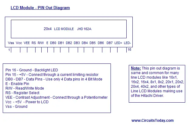
The 20×4 LCD module pin out diagram is very much same as the 16×2 LCD module pin out diagram. It is same with the number of pins, order of pins and the purpose of pins. So the interfacing circuit diagram is also very same as the 16×2 LCD module with Arduino.
Note:- The only changes you might need to make in the circuit diagram is with the current limiting resistor connected to backlight LED at pin 15 and with the potentiometer setting connected to VEE (the contrast levels of 16×2 and 20×4 modules might vary with a select potentiometer value). Rest all are very similar to interfacing a 16×2 LCD to Arduino.
Circuit Diagram – LCD to Arduino
Since the pin out structure of many popular line LCD modules like 16×2, 16×1, 20×4, 20×2, 40×2 using the Hitachi driver are similar, the circuit diagram to interface these line LCD modules to Arduino remains common. To interface 20×4 LCD to Arduino, we can use the exactly same circuit diagram of interfacing 16×2 LCD to Arduino.
Note:- The back light LED and its current requirement may vary with different types of LCD modules. The brightness you get for 16×2 LCD using a 560 ohm current limiting resistor will not be the same you get for a 20×4 LCD (or other variants like 20×2 or 40×2 or 16×1 etc). So you will have to adjust the values of current limiting resistor to suit the brightness you desire. Another change you might need to make is with the potentiometer setting connected at VEE pin which determines the contrast of LCD. The contrast you get for 16×2 LCD with a particular pot setting may not be the same for 20×4 LCD or other line LCD types (say 16×1 or 20×3 or 40×2)
So there are no changes required to make in the circuit diagram other than what is mentioned in the ‘note’ above. Let’s get to the coding part. The commands are very same as what we have written for 16×2 LCD. The only difference is in the setup() part of the arduino program, where we declare the number of columns and rows (lines) of LCD module. This declaration is what makes the program to understand the type of LCD module (number of columns and lines of modules) used in hardware.
Code – LCD to Arduino
#include <LiquidCrystal.h>

LiquidCrystal lcd(12, 11, 5, 4, 3, 2);  // sets the interfacing pins

void setup()
{
 lcd.begin(20, 4);  // initializes the 20x4 LCD
}

void loop()
{
  lcd.setCursor(0,0);           //sets the cursor at line 0 column 0
  lcd.print("20x4 LCD MODULE"); // prints characters - 20x4 LCD MODULE
  lcd.setCursor(5,3);           //sets the cursor at  line 3 column 5
  lcd.print("HELLO WORLD");     // prints HELLO WORLD
}
Okay! We have finished our interfacing tutorial and we learned how to interface arduino to LCD. If you have any doubts or you come across any problems while interfacing, please ask in comments section. In the meantime, we have the following tutorials – which you may like to read.
Interface Arduino to 7 Segment Display – learn how to interface 7 segment display to arduino with examples on interfacing 1 digit seven segment display (common cathode and anode versions) and 4 digit seven segment display (common cathode and anode versions).
Interface LCD to 8051 – learn how to interface LCD module to 8051 micro controller and display text messages on lcd screen.
34 Comments
Why these resistors like 560 nd 10k are used? please explain the design behind it?
Excellent breakdown and I am sure many readers will agree this is one of the best we explanations on the LCD display we have read, so many thanks for taking so much trouble to explain all so clearly.
Quick question – what distance can the lcd be from Arduino and still function ok when using i2c? I want to mount the display remote from Arduino as I need to use many inputs – will it drive say over 1 meter ok? Many thanks
It’s very useful & easy to understand..tnx a lot.
Could u plz make a post on an arduino project, parallel with Lcd display & matrix keypad??
This is not a tutorial on interfacing an LCD with an Arduino, this is a tutorial on interfacing the HITACHI HD44780 LCD chipset with Arduino!
These two thing are VERY different. Please learn the difference and in the future, give more thought to the title of your articles such that the title reflects what the article is actually about.
I am beginner for Arduino Uno. I tried my best for arduino Uno with display JHD 162A. with all respect but there is nothing on screan.
[1] I tried potentiometer tuning
[2] Check all circuit
[3] Program is compiled and transferred to Arduino uno board successfully.
Please help me for resolve the issue.
thanks for a good view of arduino
why so many coding ? i dun understand
My LCD is only displaying the first 8 characters in both the upper part as well as the lower part. what should i do to remove this problem and my led shows all the 16 characters in both the upper as well as the lower part??
Hi !!!
i want to make wireless notice board using arduino and bluetooth module(HC-05).
Could anyone tell me my mistake in this program,i m not able to receive data on LCD.Thanks in advance.
#include
#include
SoftwareSerial BTSerial(2,3);//rx,tx
char cmd_arr[40];
LiquidCrystal lcd(4,5,6,8,9,10);
//*************************************************
void serial_get_command()
{
int i;
char inchar=0;
int cmd_count=0;
for(i=0;i 0)
{
inchar = Serial.read();
if(inchar == ” && cmd_count 0)
{
inchar = Serial.read();
cmd_arr[cmd_count++] = inchar;
cmd_arr[cmd_count] = ‘ ‘;
}
}
if(inchar == ‘>’)
{
cmd_arr[cmd_count-1] = ‘ ‘;
Serial.print(“Cmd received : “);Serial.println(cmd_arr);
Serial.print(“OK”);
lcd.clear();
lcd.setCursor(0, 0);
for(i=0;i<=15;i++){
lcd.print(cmd_arr[i]);
}
lcd.setCursor(0, 1);
for(i=16;i<=31;i++){
lcd.print(cmd_arr[i]);
}
//serial_process_command();
}
}
}
}
//*************************************************
void setup()
{
BTSerial.begin(9600);
Serial.begin(9600);
Serial.println("System Started!");
lcd.begin(16, 2);
lcd.print("Bluetooth Based ");
lcd.setCursor(0, 1);
lcd.print(" Notice Board");
delay(2500);
lcd.clear();
}
//*************************************************
void loop()
{
serial_get_command();
}
//*************************************************
how can i interface 21 inch lcd to arduino ?? or even to pi ?
Great tutorial with examples! Save me a lot of time digging through spec sheets.
Hi iam a beginner to your tutorial. Can you tell me what programming language you are using while writing a program
For Arduino, we have to use – APL – Arduino Programming Language. Refer – https://www.circuitstoday.com/what-is-arduino
My LCD is getting powered. I have checked all the connections thoroughly. It’s all correct. But the LCD doesn’t showing any character.
It can be a problem with contrast of LCD. Adjust the potentiometer to solve this problem.
we are facing the same issue lcd display is not showing any characters even though lcd is on
check arduino pins declared and those connected to lcd
hi friends pls help me out soon im interfacing lcd(16*2, JHD 162A) with aurdino uno mine problem is that my lcd is getting powered but its not displaying the data what i’ve in code plesae kindley anyone help me out
@Praveen – Please adjust the potentiometer. This can be a contrast issue. Also make sure you have connected data lines properly to Arduino.
Please let me know – What happens to the display, when Enable Pin (E) is Enabled ?
The LCD module has Read Mode and Write Mode. Enable pin is used to switch between these 2 modes. By default, when we use LCD module for displaying characters, we write data to LCD.
Hello sir/Madam,
I want interfacing of Voice recorder and playback module(apr33a3) with aurduino and progrmming.can u help to me?
@Ajay – We shall! Very soon! Please check the website next week.
will you please send me the programme for intetfacing of voice recorder(apr33a3)/playback module & GPS using aurdiuno…..so that I can display it on 16*2 LCD
@somesh – Right now we have not worked with APR33a3 yet. We shall publish an article on the same soon.
thank a lot for these arduino project keep on posting more. can u post projects related to home automation using arduino using xbee.
@Purushotham – Thanks for the comment.We are working on more Arduino projects
I need the schematics please,am trying to send a four bit binary data to an LCD through an optical fibre cable using an arduino uno as my source of data input.
i want to know. application of digital code lock… how. it is used. and. in which. field it is applied …and how it is applied.
pls tell me. all the necessary. detail ..about this
project .
pls leave a rply
thankyou …
A digital code lock can be used for access control in offices and other such places. Basically its a door lock with a password based open/close mechanism. Refer – https://www.circuitstoday.com/advanced-digital-code-lock-using-arduino
thanks u for the these great circuits & v r impress on ur circuits…
Thanks circuits today team to provide us better circuit guidence and project.love u all team.plz alao post information regarding Rasbery pi board with simple projects.tx again.
thanks you a lot for these electronics circuits.
Thanks a TON