Interfacing SPD005G pressure sensor to arduino
This article is about interfacing pressure sensor to Arduino. The pressure sensor used here is SPD005G from Smartec . SPD (Smart Pressure Device) is a series of silicon based pressure sensors suitable for industrial as well as house hold applications. These sensors are generally available in plastic inline or dual inline packaging. SPD sensors are generally available in two operation modes namely gauge type and absolute type. In gauge type, the pressure is measured with respect to the atmospheric pressure. There is a small vent on the package for getting contact with the atmosphere. In absolute type, the pressure is measured with respect to vacuum. A small vacuum chamber is incorporated into the package during fabrication. Typical applications of SPD005G are medical systems, BP monitoring, air conditioning systems, process control, hand held pressure sensors etc.
The sensor used here ie; SPD005G is a gauge type sensor. There are actually four sensing elements inside the SPD005G and they are arranged like a Wheatstone bridge. The sensing range of SPD005G is 0 – 0.350 x 10⁵ Pa ( ie; 0 – 14.50 psi). The internal schematic and pin out of an SPD005G pressure sensor is shown below.
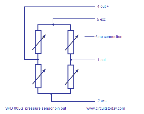
The bridge excitation voltage is given between pins 5 and 2. The excitation voltage can be AC or DC and the maximum DC voltage is 5V. The bridge output is available across pins 4 and 2. Pin 6 has no connection and it is not used. The full circuit diagram for interfacing pressure sensor to arduino is given below.
Circuit diagram.
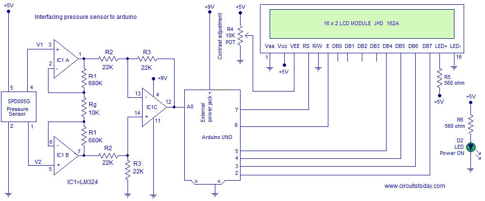
An instrumentation amplifier based on quad opamp LM324 is used for conditioning the output voltage from the pressure sensor.The instrumentation amplifier amplifies the differential voltage between output pin 4 and 1 of the pressure sensor. IC1A and IC1B serve as the high impedance input buffer of the instrumentation amplifier and IC1C sets the gain of the instrumentation. The equation for gain of the instrumentation amplifier is G=(1+(2R1/Rg))*(R3/R2). With the used components the gain here is around 137. The output of the instrumentation amplifier is connected to the analog input pin A0 of the Arduino. The Arduino digitizes this input voltage, converts it into milli volts and displays it on the LCD display. LED D2 is just a power ON indicator. Potentiometer R4 can be used to adjust the contrast of the display. Resistor R5 limits the current through the back light LED. The program for interfacing pressure sensor to Arduino is given below.
Program.
#include <LiquidCrystal.h>
int sensor=A0;
int dig_out;
float millivolt;
LiquidCrystal lcd(7, 6, 5, 4, 3, 2); // sets the lcd interfacing pins
void setup()
{
pinMode(sensor,INPUT); // sets A0 as input
lcd.begin(16, 2);      // initializes the lcd
}

void loop()
{
dig_out=analogRead(sensor); // reads the input voltage
millivolt=(dig_out*4.882);  // converts the reading to millivolt
lcd.setCursor(0,0);
lcd.print("Pressure Sensor"); // prints "Pressure Sensor"
lcd.setCursor(0,1);
lcd.print(millivolt); // prints the input voltage
lcd.setCursor(9,1);
lcd.print("mV");  // prints the"mV" notation
delay(300);       // 300 mS delay
lcd.clear();      // clears screen
}
6 Comments
The schematic is wrong.
IC1C has output on 14th pin and 13,12 for inputs.
usefull to all engineers
Using this sensor I need to convert the millivolt to read in PSI on the LCD. Any ideas on how to accomplish this and what the code would be? Any help would be greatly appreciated.
-Pete
Hi There,
I have the same problem you have now. Could you found the answer to your question?
Thank you
you need to have the datasheet of your specific sensor, find the factor and reverse the code to make it print hte pressure with the given voltage
to give option for download