In this tutorial, we are dealing with yet another interfacing technique. This time we are interfacing an RFID Reader which can read RFID Tags to Arduino. RFID is Radio Frequency Identification. An RFID reader is used to read RFID tags (which contain certain unique data stored in a chip). An RFID reader and an RFID tag, both have a coil surrounding them. When an RFID tag is shown near an RFID Reader, it collects the unique tag data (a combination of digits and characters) from the RFID tag. You will be wondering how the chip inside RFID tag gets power ? This is made possible via Electromagnetic Induction. I told you, both RFID reader and RFID tag comes with a coil in them. We power the RFID reader from power supply for reading purpose. Now when an RFID tag is shown near the reader, electromagnetic induction will take place between the coils and this powers the chip inside tag. This chip will send data electromagnetically to the reader. The reader will receive this electromagnetically transferred data and outputs it serially. Every RFID reader comes with Serial output pins. We can collect the read data through these serial pins using arduino or any other micro controller. So here begins our classic tutorial on Interfacing RFID with Arduino.
How to Interface RFID Reader to Arduino
Lets first wire the whole thing up. You may observe the circuit diagram given below. Take note of the following stuffs.
Note 1:- Power supply requirement of RFID Readers vary from product to product. The RFID reader I used in this tutorial is a 12 Volts one. There are 5 Volts and 9 Volts versions available in the market.
Note 2:- You may ensure the RFID Reader and RFID Tags are frequency compatible. Generally they are supposed to be 125Khz. You may ensure this before purchasing them.
Note 3:- There are two possible outputs from an RFID Reader. One is RS232 compatible output and other one is TTL compatible output. A TTL compatible output pin can be connected directly to Arduino. Whereas an RS232 compatible output must be converted to TTL using an RS232 to TTL converter (You can design this yourself using MAX232 IC)
So that’s all! Lets get to circuit diagram!
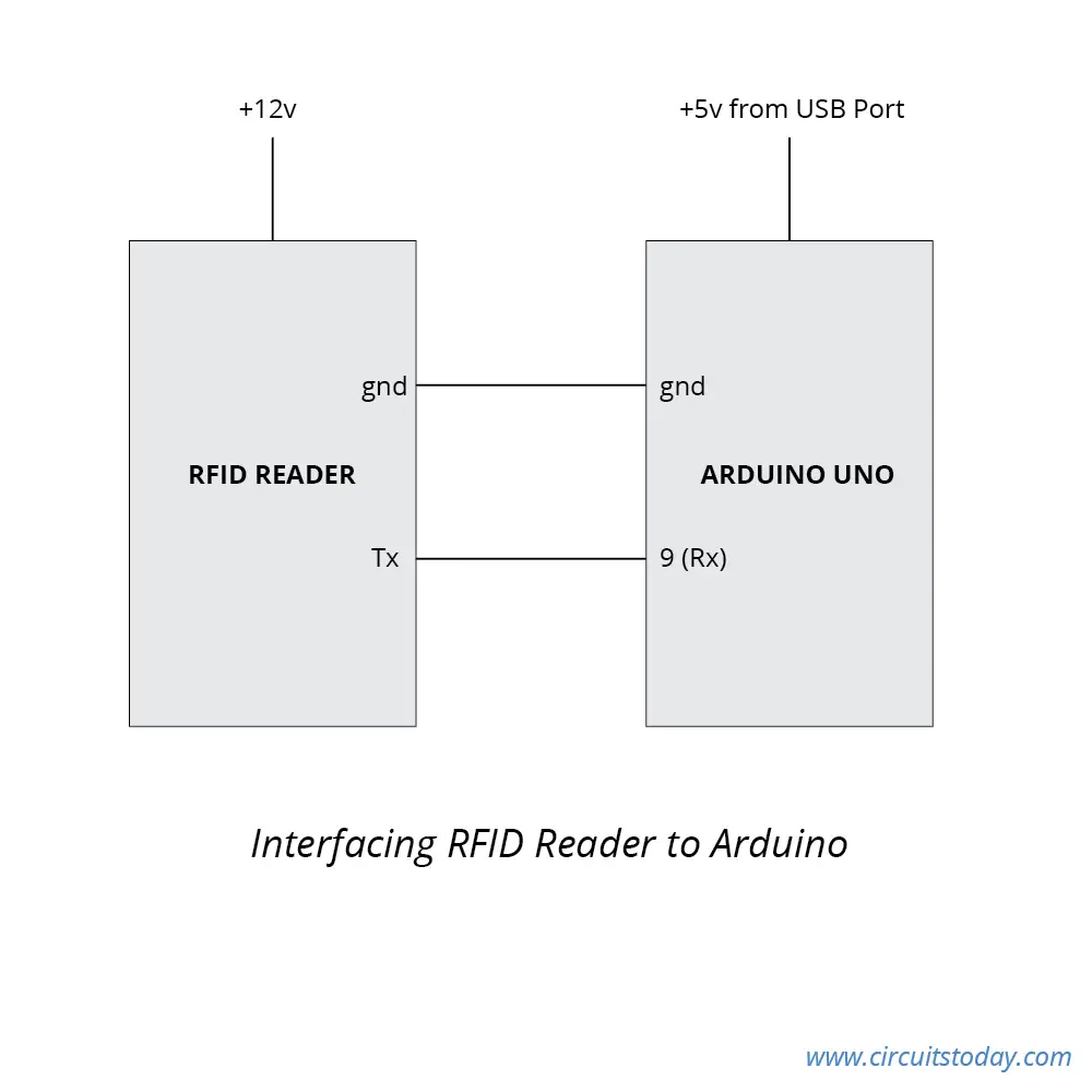
Make connections as shown. Make sure you connect Ground Pin of RFID reader to Ground Pin of Arduino. I am using the SoftwareSerial Library of Arduino which enables digital pins to be used in serial communication. I have used pin 9 as the Rx of Arduino. (You can also use the hardware Rx pin of Arduino uno – that’s pin 0). If you are new to SoftwareSerial Library, you may read my previous tutorial on interfacing GSM module to Arduino (this article clearly explains how to use Software Serial Library).
Lets get to the programming side!
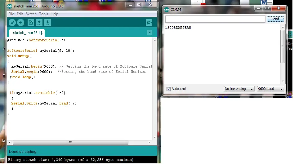
 #include <SoftwareSerial.h>

SoftwareSerial mySerial(9, 10);
void setup()
{
  mySerial.begin(9600); // Setting the baud rate of Software Serial Library
  Serial.begin(9600);  //Setting the baud rate of Serial Monitor
 }void loop()
{

 if(mySerial.available()>0)
  {
  Serial.write(mySerial.read());
  }
}
mySerial.available() – checks for any data coming from RFID reader module through the SoftwareSerial pin 9. Returns the number of bytes available to read from software serial port. Returns a -1 if no data is available to read.
mySerial.read() – Reads the incoming data through software serial port.
Serial.write() – Prints data to serial monitor of arduino. So the function Serial.write(mySerial.read()) – prints the data collected from software serial port to serial monitor of arduino.
that’s all! Interfacing an RFID Reader to Arduino is much simple than lighting an LED with Arduino! A screenshot of the read data in Serial monitor is shown below.
Now lets organize this code by storing the read data into an array and displaying them line by line in Serial monitor.
Facts to keep in mind!
1) Each RFID tag is a 12 character unique number. We read this 12 characters serially using Arduino.
2) We need a two dimensional array to store multiple RFID tags. To store 10 RFID cards, we need an array of 10 rows and 12 columns.
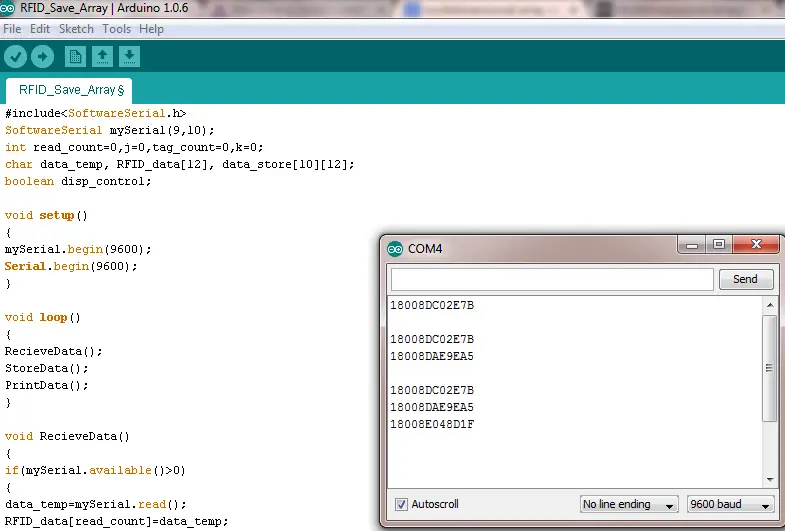
So here is the program to save upto 10 RFID Cards in a 2 dimensional array. The program collects each RFID card number and store them in a [10][12] (10 rows and 12 columns) array. These RFID card data are then printed on Serial Monitor!
#include<SoftwareSerial.h>
SoftwareSerial mySerial(9,10);
int read_count=0,tag_count=0;
int j=0,k=0; // Variabvles to iterate in for loops
char data_temp, RFID_data[12], data_store[10][12];
boolean disp_control;

void setup()
{
mySerial.begin(9600);
Serial.begin(9600);
}

void loop()
{
RecieveData();
StoreData();
PrintData();
}

void RecieveData()
{
if(mySerial.available()>0)
{
data_temp=mySerial.read();
RFID_data[read_count]=data_temp;
read_count++;
}
}

void StoreData()
{

if(read_count==12)
{
disp_control=true;
for(k=tag_count;k<=tag_count;k++)
{
for(j=0;j<12;j++)
{
data_store[k][j]=RFID_data[j];
}
}
read_count=0;
tag_count++;
}
}

void PrintData()
{
if(disp_control==true)
{
  for(k=0;k<=tag_count;k++)
{
    for(j=0;j<12;j++)
  {
    Serial.write(data_store[k][j]);
  }
  Serial.println();
}
disp_control=false;
}
}
Screenshot of the output is given below!
Important aspects of the program!
read_count – is the variable used to count 12 characters of an RFID card serially. This variable is set to zero initially and is iterated inside the RecieveData function. Once this variable iterates upto 12, the program control will enter StoreData() function. Inside this StoreData() function the each RFID card data (collected in the single dimensional array RFID_data) will get stored into the 2 dimensional array data_store. This variable is then set to zero again inside this StoreData() function to get out of this function and collect next card data.
tag_count – is the variable to count number of RFID cards read serially. This variable is iterated inside the StoreData() function. The reason is, a card data is stored only when it is read completely. This means the number of times program control completely executes StoreData() function is equal to the number of RFID cards read serially.
data_temp – is the variable to hold each single character (out of 12 characters) of the RFID Tag from serial buffer.
RFID_data – is the single dimensional array to hold a single RFID tag data completely. 12 characters of the RFID tag are fed to this array one by one from the temporary holding variable data_temp.
data_store – is our 2 dimensional array to hold each card data. It is declared as [10][12] – meaning it can hold 10 rows of 12 columns. Each RFID card data is stored in a single row. Likely 10 RFID card data are stored in 10 rows.
disp_control – is a boolean variable used to control the number of times program control executes PrintData() function. We are printing RFID card data on Serial Monitor only when a new card is read.
So that’s all about the variables used in the program. I think the program is self explanatory! Though I will skim through it.
The whole program is modularized into 3 functions – RecieveData() , StoreData() and PrintData()!
As we know, Arduino executes whatever inside its loop() function continuously, we have made intelligent use of variables to Store RFID Data and Print them according to our desire (you already understood this from my variable explanations)! So lets get to important aspects of these modules.
RecieveData() – As we know, it reads each characters of the RFID tag from serial buffer. We hold each character from serial buffer in the data_temp variable and save them one by one to single dimensional array RFID_data. We iterate our read_count variable each time a character is saved to RFID_data array.
StoreData() – is the function to store a completely read RFID card data to our 2 dimensional array data_store. You see, we need to save to 2D array only when a card is completely read. So we make intelligent use of the variable read_count here. When a card is completely read by RecieveData() function, our variable read_count will be having a value=12. So we bring an if condition and allows to store card data to 2D array only if the variable read_count==12. Once the card data is saved to 2D array, we reset the read_count variable to Zero, so that program control will not over write the stored data in 2D array. This resetting also forces program control to go and read next card data.
Note:- You may see the row key of 2D array (that is the outer for loop) is initialized using tag_count variable (see k=tag_count). This ensures the number of RFID Cards read are stored perfectly in successive rows. During the execution which saves first RFID card data to 2D array, tag_count will be Zero. This tag_count will be iterated to 1 right after the saving execution. So when program control is saving second RFID card to 2D array, tag_count will be holding value 1. Similarly while saving 3rd RFD card data, tag_count will be holding value 2. Since row keys (i.e k of of outer for loop) is controlled using tag_count variable, data will not be over written at any point of time!
24 Comments
This outer loop is not needed in store data
for(k=tag_count;k<=tag_count;k++)
Code works exactly fine without this also.
here u mention the pin 9 and 10 but in circuit you have connected only 9 th pin to the rfid reader then whats the purpose of 10 th pin where it to be connected
Im trying this code with a 125KHZ long range reader, the reader did require me to solder wires onto the terminals. when i run this code nothing happens when a card is within range. Does this mean i fried the reader when i soldered the wires to the terminals? Thanks
can you send me the arduino code to send an sms through gsm when the rfid rc522 tag is read?
Dear, I have a RFID Antenna and Arduino UNO R3, I treid connect directly and TTL way, but the serial monitor of arduino doesn’t show nothing.
I’m using a notebook with windows 10 and arduino 1.8.5.
Can you help me please?
Regards
Thanks for your time on this project.
The serial output displayed is nine lines of Rectangle Boxes, not numeric characters.
What might cause this??
Once you’ve read the data, how to show this data or write this data on another RFID?
when iam using the same code it is displaying junk value.please help………………………….
How to print data that must be already stored in arduino according to rfid reader shown?
can u plz tel the circuit diagram and programming for arduino interfacing with MFRC522 RFID ,LCD display and vioce module
Its helpful can you please provide pin diagrams also
please do you have this code for rfid in MikroC. Thanks
Can u plz add the pin configuration diagram of RDM6300 rfid with arduino uno.
Thanks.
Can you please tell the pin configuration of the same for Funduino RFID RC522 and Arduino mega.
I have tried many things but it did not work
According to Note3,
May i know what is the output of MFRC522 RFID Reader ( RS232 comptible output or TTL compatible output )