So far I’ve discussed about the micro controller basics and the compiler software. I’ve yet not written anything about programming.
ATmega32 series micro controllers support 3 types of programming
- Parallel Programming
- ISP Programming or serial Programming
- Programming via JTAG
Here ISP stands for In System Programmer. To burn a micro controller just the burning Hardware is not enough, it requires software also that would download the program present in a computer or memory device into the micro controller.
Now the software which I am talking about is named PONY PROGRAMMER 2.06. My circuit is adapted from the website of Pony Programmer. It uses PC COM PORT to download the program into the micro controller. It has a signal amplitude of +5 to +12 volt representing binary ‘1’ and -5 to -12 representing ‘0’.
The micro controller, ATmega32 is programmed using the pins meant for SPI communication. To enable programming, the microcontroller must be taken to the RESET state by pulling its reset pin LOW (Logic 0, or say 0 V). In this state, microcontroller is programmable in either mode (Parallel programming or serial programming). Micro controller always accepts 0 V as logic 0 and +5 V as logic one.
The signals transmitted from PC is not in a form that could be accepted directly by the micro controller. Those signals from PC should be made suitable for micro controller. In the programmer, Zener diodes provide necessary conditioning for the signals. It is wired in such a way that it converts ±12 volt signal to +5-0 volt signal which is suitable for the micro controller. A resistance is necessary to limit the current in the nodes of Zener diodes, without the which the Zener diode may burn off. And computer internal circuits may also receive harms.
A high signal (+5V) in the ‘Reset’ pin of micro controller brings it into operational state. A low signal (Ground) drives it into programming mode. Internal pull up resistors are provided at the reset pins and if nothing is connected to this pin, the micro controller tries to execute the program written within it. Designers can provide a resistance capacitance reset circuit, but it’s not always necessary. Whatever, a push button is used in most cases to provide reset facility. Here in the burner circuit an open collector output is provided to the reset pin and it is driven by the programmer through the port. This much is enough.
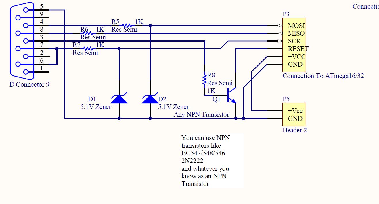
The necessary data transmission and reception work portion is handled by the pony programmer. Follow the links provided to download pony programmer. The following burner circuit can burn ATmega32 microcontroller. Connect the derived signals to the adjacent pins, attach the cable to com port, power up the device i.e. micro controller, and the micro controller is ready to be programmed.
ISP Programmer Circuit Diagram
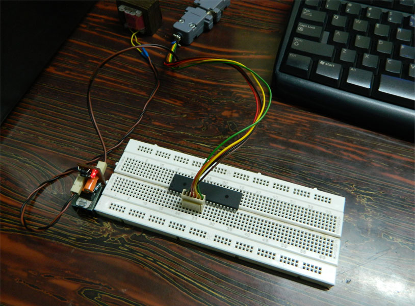
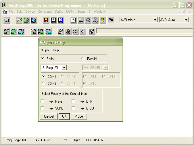
So that is how the circuit is set up. Now let me tell you that the micro controller runs upon the internal calibrated RC oscillator in the pictures. So that there is no crystal is attached. Yet the micro controller is programmable. Let us see the software settings. First of all, select the port, to which you have attached the device! And the programming device from the menu “Set Up>Interface Set Up…”. Select “SI Prog I/O”, this one provides fastest programming speed. And about the ports, it should be com port for this programming cable! Now select the port you have the cable attached to.
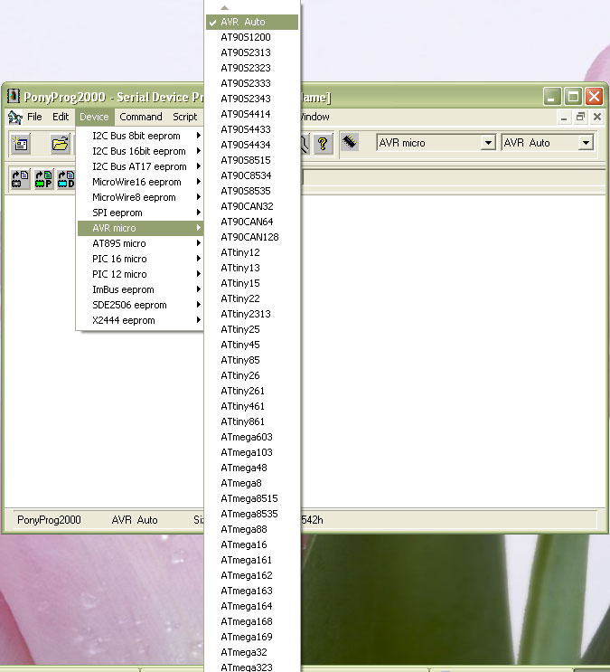
Now come to the device selection menu. Here ATmega32 belongs to the AVR family. So it is listed under “Devices> AVR micro”. Select ATmega32 as your device. Auto detection will also do.
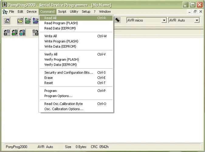
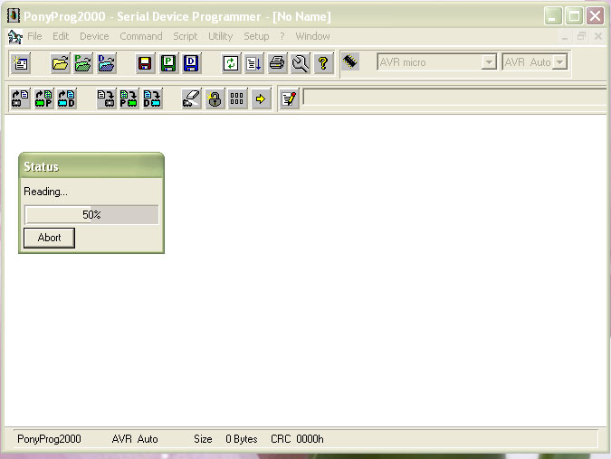
Now after this two vital things check out If your circuit is working or not. Choose “Command>Read All”
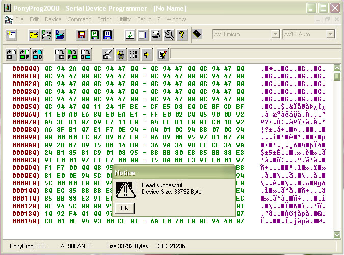
Now if you see that it is reading the micro controller without any error message, your programming cable is working and you can program the micro controller with it.
You can Burn your hex file with it (Compilers provide hex files to program micro controllers). Just open “File> Open Device File…” now an window will open, now browse for your hex file, load it into the pony programmer, and burn. Pony programmer supports click and drag operation too. That means, if you drop the hex file into the pony programmer, it will automatically catch it.
Components:
- DB9 female connector
- 2 X 1K resistors
- 2 X 5.1 V Zener diode
- 1 X 15K resistor
- Vero board
- BC 547 or any general purpose NPN transistor
- Male Relimate connector (6PIN & 2PIN)
Links for Reference:
Note: 1. Make sure that you have a COM PORT in your computer hardware and your operating system recognizes it. Check it from “Control Panel > Administrative Tools > Computer Management”. In the cascaded list pane, find the following
“Computer Management > System Tools > Device Manager > Ports (com & LPT)”. If COM ports are present under this list, this circuit will work fine. Else, look for a USB based burner.
Note 2. This burner will work fine for ATmega16 too. For ATmega8, you need to connect the signals to the respected pins.
Note 3 .You can omit the male 2-PIN Relimate connector
Bibliography
Lancos.com and Atmel
61 Comments
rakesh…
you mention in this circuit have 4 resistor but listed in 3 resistor so please which resistor suitable in the circuit
please each resistor mentioned
Hello,
Can I also program to Atmega328p by ISP Programmer Circuit Diagram?
Can I use this circuit with USB to serial port cable???
could you please explain how to convert this circuit to use with usb using ft232. If we use a rs232 to usb converter, doesn’t it do the same?
Yes. It would do the same. You need to carefully look for the signals and patch them.
It is so nice of you if you could explain only the circuit. I’m bit confused with how I connect those reset and sck pins. Please
I am new user for this programmer that is work with atmega8 ?
when i will use ATmega8,what hardware devices and circuit ,i should use.please u tell me.
Hi,
The hardware is all same. You just need to connect the MOSI, MISO, SCK and RST Signals to ATmega8 properly.
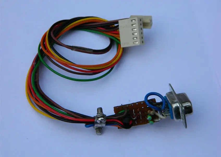
Why use transformer in the circuit and where place we connect it.Please tell me definitely.
That is for power supply.
when i will use ATmega8,what hardware devices and circuit ,u should use.please u tell me.
Thanks for the programmer it was just what I needed.
Just a tip to anyone trying to read a programmed chip.
if it doesn’t read and gives an error, the chip possibly has
its oscillator set as external. This was my case, problem
solved by adding a crystal (atmega16 pins 12 and 13 and a 22pf cap from each pin to ground)
To the hardware.
Sir is there code for water proof temprature sensor (DS18B20) with AVR micro controller atmega 32???????
will this circuit work for atmega16?
Worked for me with atmega32 + atmega16
How can I connect DB9 female connector with my laptop?
Nasimul,
Please scroll down the page, I suggest you the same as I suggested to shiva ghosh
hello, can i use this device to program atmel 89c51?
89C51 needs parallel programming, and you need a parallel programmer specialized for it. I recommend arduino pro mini + usb+ttl converter [ with dts ] if you are serious about embedded systems programming but want to save money
Sir, can you please tell me cant I use a ttl usart to usb converter to build the programmer circuit rather than using a DB9 port and Usart to Usb cable,
but in such situation, I need to what pin should be connected to RXD and TXD of ttl device…is it MISO and MOSI ? while making the RESET pin always pulled down to ground.
can I leave other ports? what is SCK port for?
Siva, you need a usb-ttl converter with dtr out available in the breakout.
it is because recently I bought an ATmega32 and paid the storekeeper for the transferring of the hex file I obtain from a friend. Unfortunately, I did not get any positive result, simply there was no output of my external interrupt project. As far I I know they used Arduino to burn it using the hex file I gave to them. The code is as below.
My project is to detect external positive dc volts ( 5v ) and it will consequently cause to light up LEDs sequentially with specific time intervals.
a) Specifically if the switch is pressed (positive volt signal), the IC should produce a 1-time sequential output of 8 LEDS (LED1 lights up. then after 2 seconds the LED1 turns-off. Then LED2 should turn-on for 1 minute, then turn-off. Then the LED3 should turn on for 2 seconds then turns-off. Then the same with LED4,5,6,7 and LED8 should turn-on for 1 minute then turns-off. During this period (from LED1 to LED8), the system must ignore any positive input. But after fully implementing the 8 outputs of the LED, only by this time it will again the system should implement another positive external signal.
b) The sequential output of IC must not be interrupted within that period (from LED1 to LED8 ) meaning it should lock itself. It should ignore any positve signal from any external input.
c) Only use Atmega32A-PU because this is the only available chip I have.
d) Please correct the C code if there’s any to correct.
e.) Please provide the correct HEX file also.
f.) Please note that this Atmega32A-PU will be programmed using Arduino by the electronic storekeeper.
g.) Please give instruction about the Fuses and bootloader if necessary as I have no ideas about this, and maybe the storekeeper might also have no idea, either.
h.) is crystal oscillator not needed in the circuit?
Here’s the C code: (please correct)
Attached are: circuit diagram & hex code (please correct)
*********************************************************************************/
#include
#include
#include
#define LED_PORT_DIR DDRC
#define LED_PORT PORTC
#define LED_DATA (0x01)
#define GLOW_LED(times) (LED_DATA << times)
#define DELAY_MS (2000) // in milli seconds
#define MAX_DELAY_MS (10000) // in milli seconds
#define LED_OFF (0x00)
/***** Function To Initialize Ports*****/
/* PORTC to output */
void init_ports()
{
LED_PORT_DIR = 0xFF;
}
/***** Function To Initialize Interrupts*****/
void init_interrupts()
{
cli(); //Disable Global Interrupts
GICR =(1<<INT0); //Set Bit6 of GICR to unmask INT0 interrupt.
MCUCR =(3<<ISC00); //Configuring MCUCR for Rising Edge interrupt for INT0
_delay_ms(MAX_DELAY_MS);
sei(); //Enable Global Interrupts
}
/***** Interrupt Service Routine For INT0*****/
ISR (INT0_vect)
{
static int i = 1; // to disable it for first time
if (!i) {
for (i = 0; i < 8; i++) {
LED_PORT = GLOW_LED(i);
if ((i+1) != 8) {
_delay_ms(DELAY_MS);
}
else{
_delay_ms(MAX_DELAY_MS);
}
}
}
i = 0;
LED_PORT = LED_OFF;
}
/***** Main Function *****/
int main(void)
{
init_ports();
_delay_ms(MAX_DELAY_MS);
init_interrupts();
while(1)
{
}
}
ok, I guess I come to understand what you want so say. Together it will loo like: you press a key, and a light sweeps through the array.
Well Here how you do it:
ISR(INT0_vect){
int i=7;
for (;i>=0;i–){
LED_PORT=(1<<i);
_delay_ms(DELAY_MS);
LED_PORT=0x00;
}
}
Please check for the symbols. It have been many days since I used embedded C
hi sir, any comments why FUSES and bootloader are not mentioned in programming this particular uC and programmer?
can you explain please. thanks
Hi uelman, I didn’t made any chages to he fuses. The default works fine.. But for better performance, you might consult the Atmel datasheets.
followed all your instructions. but i couldn’t get any positive result. ponyprog doesn’t detect my device. is there any possible way to check the condition of my micro controller? could you please help me?
See, there are lot of hand made thing need to work correctly in this circuit. First check if the burner is providing the signals or not.
if it works… check the patching on the bread board
Hi,
Can you please let me know the approximate cost of COMPort and USB burner and any picture of what it looks like.. I’m not able to identify it from the pictures above.
Thanks
See, this will not work with external com ports…
For the programmer, The system needs a direct access to the Com port
Dear sir,
could i use a voltage supply of 4.9 volt and how to check whether port is in working condition or not.
thank you
Yes, ATMega Series Micro controller would be able to tolerate that
Rakesh any way of burning the ATmega32 chip from usb port of laptop?
Yes, It’s possible. But there one intermediate IC is required. There ready-made boards are available in the market and over the internet too. It’s better to grab one than making one by yourself.
Google for USBASP. you can find it in ebay
Hi Sir Rakesh,
I tried AT89S52 but it displays “Device not Responding” when executing “Read All” and “Write All” commands. What seems to be the problem? And on the Picture above what voltage did you use and where did you connect the voltage terminals at the breadboard?
Leo,
Working with the 89S52 little bit tough. Programming it, is tougher. That’s why I avoided to work with it. If your circuit is fine, try selecting the appropriate device from the drop down list as shown before. I hope that will help.
i love your feedback.now i get my answer.now i am going to start my project.it is very useful information.many website is telling about it but no one telling very clearly like your website.thank you dear rakesh and circuitstoday.com.i love your website.thankyou.
one more question, can i burn atmel89s52 40 pin with this isp programmer.i shall be very thankful to you.
I have not tried 89S51 to burn with pony programmer(Not there is support for 89S52 and 89s53). I refer you to go to the pony programmer website. Schematics are there. You can follow them. I actually never felt any ease of using 8051 architecture based micro-controllers.
dear sir,i am new in micro controller.i can understand that p3 is connection to atmega 16/32 but what is p5 header two.plz tell me soon.
This P5 gives an option to skip a breadboard for programming the ATmega16/32. It’s optional and you can remove it from the circuit, It doesn’t harm at all. But, then, you need to wire the micro controller mounted on the breadboard. And then you can supply it with 5V
you can skip calling me sir, you can directly address me as Rakesh.
Hi,
I just built the isp programming circuit using the provided schematic for programming my atmega 32L.
however, when i try to “read all” using pony prog, i get an error message “Device missing or unknown device (-24)”. If i ignore the message, the device ends up reading the hex file in the microcontroller.
How can i avoid the error message?
regards
While making this cable, I faced this problem lot of time. In case there is something wrong with the connection or setting, this message comes up. This won’t show up only if the the Pony programmer recognizes what is the the device that is connected to. Try making the following checks:
1> First of all check the settings in the pony programmer, suppose you are connecting ATMega8, select the same from the device menu. The read hex file must not be all FF in this case.
2> The port selected for programming must be proper. In this case it must be on of the physical com ports.
3> Check if the signals available in the output of the circuit. you may use LED’s to detect the signal.
4> Check if at the time of reset, the transistor turns on. Or you may try connecting the RESET pin to ground and then program.
Hi Rakesh,
Thanks for the reply. I went through my circuit and found that i had not connected my signal’s ground correctly. I did the troubleshooting and it is now ok.
in the first read all nothing error but all the contents are FF.What can i do?
dear sir,
in the circuit diagram shown R5,R6,R7,R8 As 1k resistors,but the Components list shows it,
2 X 1K resistors,
1 X 15K resistor,
which one is the right one?
You can replace the 1K resistor with any resistor valued between 1k to 10k. Sorry for late reply, I have been really busy these days.
can we use a db9 to usb connector to program it from laptop?
Sadly- No. The USB to RS232 converter will not work. But the chip used in the converter can be used to design a ISP Burner. The ic used is FTDI chip’s FT232. And it was exclusively used in Arduino boards till 2011. The Chip and arduino’s driver work fine. But that chip, USB-Serial driver and PONY-PROG doesn’t mix.
Whats the wattage of the resistor? can i use AVR STUDIO FOR THIS?
1/4 or 1/6 watt is fine.
And About AVR studio Compatibility. This burner cable cannot be driven from the inside of the AVR studio. But, It can download the hex file generated by AVR studio.
Hex file is generated after you build the code. and it can be found inside the “\\default” directory.
the flow is as follows
Create a project in avr studio -> Write your program -> build the program -> find out the Hex file -> open Pony programmer -> load the hex file -> attach the cable to PC and connect the other end to the micro controller -> Select options in the pony programmer -> download the hex file into micro controller.
YOU’RE COOL MAN 😀 THANKS 😀 were so excited to try this 😀
Thank you for your appreciation!
@Anish
The switching between normal mode and programming mode is made by the reset pin. The reset pin has two functions. If it is tied high, the micro controller will run in normal mode. this pin is internally pulled up by a resistor. So even if users are not connecting any resistor, the micro controller will run in normal mode
And when the RESET pin is tied low, the micro controller enters programming. Two types of programming can be made in this mode. ISP and parallel programming.
Oh, sorry i didn’t read the post completely.I have another question though. Will a serial to usb converter work with this ISP programmer?
Hi rakesh,
So, the atmega32 does not require the programming voltage. But how it switches between programming mode and normal mode? like the PICs
Ow, sorry. About the voltages, I meant that 13.2V. ATmega32 doesn’t need it. Some micro controller requires this voltage for some modes of the programming.
@Shurid
ATmega32 doesn’t need any voltage as some of the ATtiny micro controllers or some PIC micro controllers need it. The transformer is required for the circuit 5V regulator, it supplies power to the micro controller.
And about the Zener diodes, It doesn’t actually converts the voltage. The term “Shaping” is more appropriate for it’s operation. A Zener diode brings down the voltage between two nodes to the Zener diode’s voltage rating by draining current through it.
Another thing, Rakesh, that transformer (in image 3), have u used it for supplying the programming voltage (~13.2V) to the uC ?
rakesh …
“Zener diodes provide necessary conditioning of the signals. It is so attached that it converts ±12 volt signal to +5-0 volt signal which is suitable for the micro controllers …” — can a zener convert voltages ? or are u talking about level down the voltage ??