Interfacing LCD Display in 8bit Mode
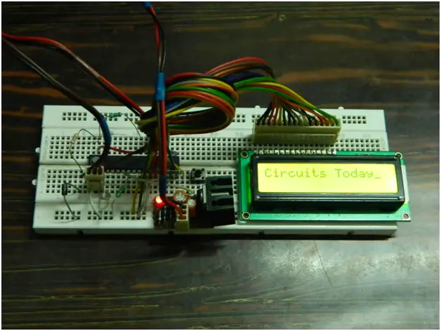
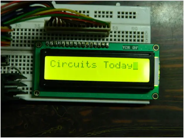
I’ve already discussed about the LCD display in a note here in this website. You can read the Note on character LCD Display here. Now let us come to the interfacing side of LCD. Let us see the 8bit mode interfacing of the LCD display with an AVR micro controller first. I have added two circuits in this post 1) Interfacing LCD with Avr Atmega8 and 2) Interfacing with Atmega32. Towards the end you can see the real life display as an image where I displayed characters“Circuits Today” 🙂
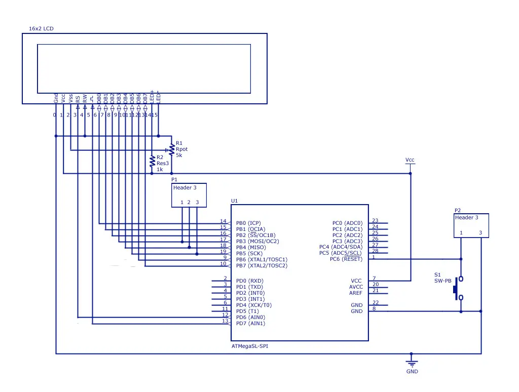
Here to interface LCD with Avr, an 8 bit data bus is required. In addition we need 2 bit control bus for write only mode or 3 bit control bus for Read plus write mode. Connect pin 1 of the LCD module to ground, pin 2 to +ve supply. Connect a Pot (2 to 5 K Ohm) across the supply and ground. Connect the middle pin of the pot to pin3 of LCD module. If you want to light up the back light, connect the –LED pin to ground. Connect the +LED pin of the LCD to the +ve supply using a resistor. Figure below is the two circuit diagrams!
1) Interfacing LCD with Atmega8 (in 8 bit mode)-Circuit Diagram

2) 1) Interfacing LCD with Atmega32 (in 8 bit mode)-Circuit Diagram

Now, I’ve written up two routines for two separate cycles. One is used to transfer data (or character). Another sends command. In C code, they are listed under the functions ‘LCD()’ and ‘LCDcmd()’ respectively. To prevent crash of data, we must allow the LCD to complete execution of each operation. Here we will be using delay loops available from the AVR studio Library. Each instruction or data takes at least 40uS to get executed. Longest wait loop is of 1.65mS. For further details, read my note upon LCD display (Wait a minute. It shouldn’t be ‘LCD display’, instead ‘LC display’. But ‘LCD display’ is widely used ) & AVR Library overview for beginners. Let’s check the code
One more thing, it is better that to copy and paste this code in notepad (Or word pad or MS word) and check this code.
//-------------------------------------------------------- Start

#include

#include
#define DPORT PORTB //Define Data port
#define DPDDR DDRB
#define CPORT PORTD //Define Signals port
#define CPDDR DDRD
#define RS PD6 //Signal Pins, Reset
#define EN PD7 //Signal Pins, Enable
//Pre-defining Commands
#define LCDClear 0x01 //Clears LCD Display
#define LCD8bit 0x38 //Sets up LCD in 8bit mode
#define LCDCursorOn 0x0f //Enables Cursor
#define LCDSeek00 0x80 //Seeks the pointer to the begeining
void LCD(char ch);
void LCDcmd(void);
void LCDInitialize(void);
int main()
{ DPDDR=0xff;
CPDDR=0xf0;
_delay_ms(2000);
LCDInitialize();
LCD(‘C’);
LCD(‘i’);
LCD(‘r’);
LCD(‘c’);
LCD(‘u’);
LCD(‘i’);
LCD(‘t’);
LCD(‘s’);
LCD(‘ ’);
LCD(‘T’);
LCD(‘o’);
LCD(‘d’);
LCD(‘a’);
LCD(‘y’);
return 0;
}
void LCD(char ch)
{ DPORT=ch; //Put values to ports
CPORT=(1<<RS)|(1<<EN); //Signaling to send data
_delay_us(10);
CPORT=(1<<RS)|(0<<EN);
_delay_us(45);
}
void LCDcmd(char ch)
{ DPORT=ch;
CPORT=(0<<RS)|(1<<EN); //Signaling to send commands
_delay_ms(10);
CPORT=(0<<RS)|(0<<EN);
_delay_ms(45);
if(ch==0x01||ch==0x02) // If commands are LCD Clear or
// LCDSeek00, delay 2mS
_delay_ms(2);
}
void LCDInitialize(void)
{ LCDcmd(LCD8bit);
LCDcmd(LCDCursorOn);
LCDcmd(LCDClear);
LCDcmd(LCDSeek00);
}
//——————————————————– End
Now I’ve used Lots of crazy symbols in my program. Here is a summary.
- In C, ‘0x’ prefix represents a hexadecimal number. ‘0b’ represents binary.
- ‘|’ is the bitwise ‘OR’ operation. Here, 0b0010|0b0110=0b0110.
- ‘||’ is the Logical ‘OR’ test. If in statement ‘A||B’, if value of either or both of the operand is NOT Zero (or True), then the statement result is TRUE.
- ‘≪’ stands for Bitwise right shift operation. Here, 0b0001≪2 =0b0100.
- ‘≫’ stands for Bitwise left shift operation. Here, 0b1000≫1 =0b0100. Just for your knowledge, I’ve not used them in this article.
So that was basic version of the code. Let’s see some better functions to be compiled.
//-------------------------------------------------------- Start

#include

#include
#define DPORT PORTB //Define Data port
#define DPDDR DDRB
#define CPORT PORTD //Define Signals port
#define CPDDR DDRD
#define RS PD6 //Signal Pins, Reset
#define EN PD7 //Signal Pins, Enable
#define LCDClear 0x01 //Clears LCD Display
#define LCD8bit 0x38 //Sets up LCD in 8bit mode
#define LCDCursorOn 0x0f //Enables Cursor
#define LCDSeek00 0x80 //Seeks the pointer to the begeining
void LCD(char ch);
void LCDcmd(void);
void LCDInitialize(void);
void printStringLCD(char *str);
int printIntLCD(unsigned int i);
int main()
{ DPDDR=0xff;
CPDDR=0xf0;
_delay_ms(500);
LCDInitialize();
printStringLCD(“Circuits Today”);
_delay_ms(5000);
LCDcmd(LCDClear);
prinStringLCD(“Print an Integer”);
LCDcmd(0xc0);
printIntLCD(990);
return 0;
}
void LCD(char ch)
{ DPORT=ch; //Put values to ports
CPORT=(1<<RS)|(1<<EN); //Signaling to send data
_delay_us(10);
CPORT=(1<<RS)|(0<<EN);
_delay_us(45);
}
void LCDcmd(unsigned char ch)
{ DPORT=ch;
CPORT=(0<<RS)|(1<<EN); //Signaling to send commands
_delay_us(10);
CPORT=(0<<RS)|(0<<EN);
_delay_us(45);
if(ch==0x01||ch==0x02)
_delay_ms(2);
}
void LCDInitialize(void)
{ LCDcmd(LCD8bit);
LCDcmd(LCDCursorOn);
LCDcmd(LCDClear);
LCDcmd(LCDSeek00);
}
void printStringLCD(char *str)
{ int i=0;
while(str[i]!=’\0′)
{ DPORT=str[i]; //Put values to ports
LCD(ch);
i++;
}
}
int printIntLCD(unsigned int i)
{ static int a;
a=0;
if(i!=0)
{ printIntLCD(i/10);
LCD(‘0’+i%10);
a++;
}
return a;
}
//——————————————————– End
Photographs of LCD Interfacing
And you want more focused one?


14 Comments
Hello,
I am getting incomplete character display on my 16×2 LCD (1602A)
I do not have an oscilloscope to check signals
I am using the Ready for PIC Dip 40 with socket PIC18F45k22 developement board.
I grounded the unused pins D0 – D3 of the LCD as i am using it in 4-bit mode
To get it to finally display, I re-checked my wiring and it started working. It wasn’t the LCD because I swapped it out with spares I have and still get the same results.
Right now I have gotten it to display on the LCD but:
The output is not displaying all characters. Its missing some characters (it displays “Hell wrd”) instead of displaying the full “hello world”. Each time I reset it using the on board reset button, it changes to another set of uncomplete characters: “Hlo ol”……”Hll rld”……”Hll ol”.
I am using MikroC pro for PIC v 7.2.0
Below is my code:
//start code
sbit LCD_RS at LATD5_bit;
sbit LCD_EN at LATD4_bit;
//sbit LCD_D0 at LATD6_bit;
//sbit LCD_D1 at LATD7_bit;
//sbit LCD_D2 at LATA0_bit;
//sbit LCD_D3 at LATA1_bit;
sbit LCD_D4 at LATD0_bit;
sbit LCD_D5 at LATD1_bit;
sbit LCD_D6 at LATD2_bit;
sbit LCD_D7 at LATD3_bit;
sbit LCD_RS_Direction at TRISD5_bit;
sbit LCD_EN_Direction at TRISD4_bit;
//sbit LCD_D0_Direction at TRISD6_bit;
//sbit LCD_D1_Direction at TRISD7_bit;
//sbit LCD_D2_Direction at TRISA0_bit;
//sbit LCD_D3_Direction at TRISA1_bit;
sbit LCD_D4_Direction at TRISD0_bit;
sbit LCD_D5_Direction at TRISD1_bit;
sbit LCD_D6_Direction at TRISD2_bit;
sbit LCD_D7_Direction at TRISD3_bit;
void main() {
TRISD = 0; //CONFIGURE PORTD AS OUTPUT
ANSELD = 0; // PortD as digital
Delay_ms(2000);
Lcd_Init(); // initialize LCD
Delay_ms(5);
Lcd_Cmd(_LCD_CLEAR);
Delay_ms(5);
Lcd_Cmd(_LCD_BLINK_CURSOR_ON);
Delay_ms(5);
Lcd_Cmd(_LCD_CURSOR_OFF); // blink cursor
Delay_ms(5);
Lcd_Out(1, 1, “Hello World”);
while (1)
{
}
}
//end code
sir what to do to print in next line and also i want to interface 20×4 lcd with avr .. what changes should i make in program
Well i can’t seem to get it work. I have defined the data port to PORT D and the signal port to PORT B. I set the RS to PB2 and the EN to PB1. All my connections in the board and the LCD are correct. I checked them. When I load the program it fills the first line with all dots. I don’t know why is this happening.
why did you use the the resistor ri and r2 (you can see in image of lcd interfacing )
can’t we give the rw signal directly by connecting this pin to the any pin of micro controller by define
We have tied the r/w pin of the lcd to +5V. It will keep the LCD in write mode always. We are not using Read mode in LCD. So to keep the whole project simple, we have connected it to +5V. [It reduced the complication of the code, and circuit as well, plus it we can give up using one more pin]
1. #define DPDDR DDRB
2. void LCD(char ch)
{ DPORT=ch; //Put values to ports
CPORT=(1< _delay_us(10);
CPORT=(1< _delay_us(45);
}
3. LCD(‘0’+i%10);
sir tell me the mean of these things
Too many questions in one query.
Let me answer first thing first. The symbol DDRB is predefined in the avr gcc library. And as you can see, we used a combination of header files to keep the main C program short. If we intend to reuse the code, but if in circuit we had to change the port [which actually happened, I used the same code for ATmega16 and 32], we would have to make changes in the header files. Which would reduce the code reusing. So we decided to define another symbol in the code.
Let me answer the second question.
First I wlould like to tell you that due to some problem with the word press editor, I was not able to present the program symbol by symbol. It is very much required but I failed. It was [and still is] not exact symbol by symbol code. The function you mentioned was quiet like this:
void LCD(char ch){
DPORT=ch;
CPORT|=(1<<EN);
_delay_us(10);
CPORT&=!(1<<EN);
_delay_us(45);}
We used DPORT as in Data PORT, and CPORT as in Control PORT. EN stands for ENable. The intention is to make the data available in the data bus and pulse the EN pin once. It will write one character in the LCD Screen one at a time. The delay is used to provide sufficient time to the LCD to get ready to receive a character and to write the character to LCD.
Answer No.3.
This particular portion of the code is a part of the function that prints an unsigned integer variable onto the LCD display.
Now the question is. WHY THE HELL I NEED THAT PART?
Simple, there is a difference between how we represent a number in symbols [e.g. 1241 214 9432 428 etc. etc.] and how it is stored in a register
[e.g. 0b0000010011011001 0b0000000011010110 0b0010010011011000 0b0000000110101100 etc. etc.]
So we had to convert the value of the variable into symbols.
Now, we converted the variable LSB first. We divided it with 10 [we represented the number in decimals] and used the reminder to compute the ASCII character of the reminder. Simple.
@ Ramit Debnath
We are having some issues on the character coding! The website uses UNICODE character set where as the c code is usually written in ASCII format. And you can avoid the F_CPU error by providing the CPU OPERATING FREQUENCY from “Menu bar>Project>Configuration Options>General” and providing the operating frequency. Or you may place the statement like this
//————
#define F_CPU 1000000
#include
……….
//————
And, If you are using delay loop. You cannot provide a variable as an argument to the _delay_ms() or _delay_us() function. It would generate an error. The value supplied must be constant and must be of integer type.
The below problems are solved. But now its showing build error and something delay character should be integer
There were no hidden character,but still error\ 240 is showing.
How to resolve it?
Avr studio 5.1 shows that
#warning “F_CPU not defined for
and there are lots f stray errors such as
Error 2 stray ‘\240’ in program
whats the meaning of these errors? and how to resolve them?
please reply ASAP.
Just add this line below :
#define F_CPU 1000000