Description.
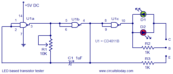
Here is the circuit of a very simple transistor tester which used two LEDs for displaying the condition of a transistor. Both PNP as well as NPN transistors can be tested using this circuit. Quad 2 input CMOS NAND gate IC CD4011B is the heart of the circuit. Out of the four NAND gates inside the IC, only three are used here and they are used as NOT gates by shorting their input terminals. Gates U1a, U1b, resistor R1 and capacitor C1 forms a square wave oscillator. The frequency of this oscillator can be adjusted by using R1. The output of the oscillator is inverted using the gate U1c. The inverted oscillator output is connected to the base of the transistor under test through the resistor R2 and the non inverted oscillator output is connected to the emitter of the transistor under test using the resistor R3.
The status of the LEDs D1 and D2 reveals the condition of the transistor under test. If red LED is ON, It indicates that the transistor under test is a good NPN. If green LED is ON, it indicates that the transistor under test is a good PNP. If both LEDs are ON, it indicates that the transistor under test is short. If both LEDs are OFF, it indicates that either the transistor is bad or you may have connected it incorrectly.
Circuit diagram.
Notes.
- The circuit can be easily assembled on a Vero board.
- Use 5V DC for powering the circuit.
- All unused pins of the IC must be connected to ground.


17 Comments
Is there a reason you use a NAND gate IC if you’re just shorting them out into NOT gates? Couldn’t this circuit be built with a IC 7404 (NOT gates) instead?
This Circuit is Cheap Simple and Useful..Thank You so Much For A Great Little Handy Dandy Project!!!!
only pnp transistor make glow to green line red led is not glowing when npn is connected .. what is problem there ?
Green LED on = PNP,,, Red LED on = NPN Awesome Circuit!! Worked First Time!!
i have tried the connection bt the led’s are nt glowing up, can any1 tell wats d problem exactly??
May be ic is dud. or check your wiring thoroughly. It is a very simple circuit and it should work.
What we can use instead of VK200J in 2km fm transmitter?
Any RF choke from 50uH to 250uH
This is The BEST Transistor Tester I Have ever seen!!! Basically The 4011 does all the work,,,WOW!!!!!!
Nice Design,,,Cheap Simple Effective,,, Thanks!!!!PS****I used a 10K resistor( To keep costs down) and it worked great!!!
very nice.. keep it up… i need simple capacitor and inductor meter circuit using LEDS.
frndz please tell me that in this circuit what is the values of R1 and R2……
R1=10K while R2=R3=1K
I impress very much with it.
Very very useful and fantastic
The Parts Are Very Cheap..Resistors 2 cets each and 4011 for about 40 cents!!!
cets=cents oops!!!
happy days