LED Scrolling Display Board
This article explains the steps involved in designing a scrolling message LED Display. The following features of the display are explained in the article.
- Framing Alpha-Numeric characters and special characters
- Multiplexing the matrices
- Serial mode of data distribution using shift registers
- Static text display
- Scrolling text display
- Mode selection between static and scrolling
- Increasing and decreasing the speed of scrolling in real-time
This article focuses on displaying a static text on an LED board. The texts and characters to be displayed are pre-programmed. The same project has been modified in such a way that the texts and characters o\to be displayed can be remotely edited using a bluetooth feature. Click on the link below to know more about it.
Refer: Bluetooth Based Programmable LED Message Board Circuit
Scrolling LED Sign – Output Video Demo
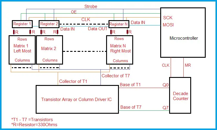
LED Scrolling Display Board – Block Diagram
LED Dot Matrix – Internal circuit Diagram
The name itself infers that the LEDs are connected in a matrix format i.e., in rows and columns. The matrix can be formed with the desired number of rows and columns. However, 7X5 (5X7) and 8X8 dot matrix displays are readily available as modules. The designer can use these modules or can build an array by using individual LEDs. As the LEDs have two terminals, the matrix orientations are of two types. The row terminals are of Anode type and the column terminals are of Cathode type vice-versa or the row terminals are of Cathode type and the column terminals are of Anode type. Below are the images of the Matrix displays for the common anode and common cathode types.

Here is a typical data sheet of Dot matrix displays with the above images.
Refreshing the Matrix Display
From the circuit diagram of the matrix displays, it is clear that any LED can be controlled only by the Row and Column terminals. So, in order to show a symbol or character through the LEDs, it is not possible to continuously turn ON all the LEDs corresponding to the character all the time. The LEDs should be addressed and controlled using individual pixels of the matrix.
The matrix displays are similar to the Matrix keypads and are interfaced in the same way, the only change is that both the rows and columns are viewed as Output terminals. So, to display a character on the matrix, the information should be sent to the matrix either column by column or row by row. This is known as refreshing. Below video shows digit zero at a slower refresh rate.
Let’s discuss the column by column type of interface for an 8X8 Matrix display. Let the columns be named from C1 to C8 and the rows from R1 to R8. In order to display a character, C1 is enabled and the rows that are required to show the character are enabled/turned ON. In the above video the digit zero is shown on the matrix. So, when C1 is enabled, R3 to R7 should be turned ON. Similarly, when C2 is enabled R2 and R8 should be turned ON. Remember that, before enabling C2 the C1 should be disabled and all the rows must be turned OFF (Rows is Optional). This is done by decade counter in our circuit.
Framing the Characters Array for LED Scrolling Display
For the refreshing of the display as discussed above, the characters are framed as two-dimensional arrays. The first dimension is used to address the character and its length or size is equal to the number of characters. The second dimension contains the information of rows corresponding to the enabled column or the information of columns corresponding to the enabled row. The array containing alpha-numeric and special characters is provided below. This data corresponds to Column Cathode type dot matrix display. Below is the image showing a character using asterisks.
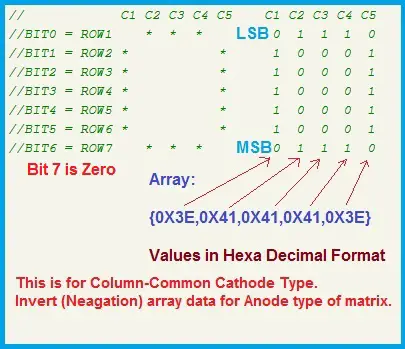
Download - Code of Characters Array
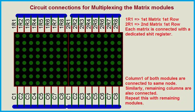
Multiplexing the Matrices
An 8X8 matrix contains 16-Pins, 8 pins for 8 rows and 8 pins for 8 columns. So, to interface a matrix we need 16-pins of the microcontroller. But, it can display only one character at a time, i.e., length of the text is only one complete character. In order to show a line of characters, a number of matrices have to be placed side-by-side and every matrix should be interfaced with the microcontroller. For example, consider that we are using ten matrices and then 160-pins or 20 8-bit I/O Ports of the microcontroller are required to operate the matrix array.
When a large display is required to show multiple characters as a line of text, a number of 8X8 matrices are placed side by side. Considering the column by column type of interface, unique columns of each matrix are shunted i.e.., C1 of all the matrices are connected together and the same is done for C2 to C8. Now, 8-Pins are required to control the columns of all the matrices of the display array.
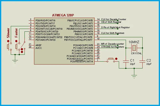
We can still reduce the number of pins to control the columns. This is possible by using a Decade counter. The counters like HCF4017, CD4017 or a similar IC can be used to control the columns. The microcontroller has to provide a clock pulse to increment the count from one of its I/O Pins and also it has to reset the counter during start-up and whenever required on-the-go. So, totally, 2 I/O pins are required to operate the decade counter which will control the columns of the entire display array.
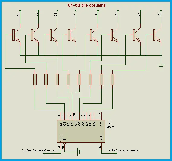
A driver IC or transistors are required to withstand the current. Transistors like C8050 or SS8050 offer 1.5A collector current continuously. Other transistors like 2N2906, 2N2222, 2N3904 etc.., offer around 600mA. The maximum collector current required depends on the type of module and size of the LED selected. The data sheet of the matrix module contains the data related to typical LED current. Using this current we can calculate the maximum collector current required.
- Iled = Typical current drawn by LED
- 8*Iled gives maximum current drawn by a column of the module (8X8)
- 8*Iled *(No.of Modules) gives the current drawn by column1 of all the modules, as the modules are multiplexed, unique columns are shunted.
Thus, the maximum collector current = 8*Iled *(No.of Modules)
Now, let’s reduce the I/O Pins required to control the rows of the display array. This is done by using ‘Serial-In Parallel-Out’ shift registers. This register receives the input data serially and loads data at its output port i.e., at the parallel outputs. By using this type of data transmission, only 4-Pins of the microcontroller are required to send the rows data to the entire display array.
Serial Data Transmission from the Microcontroller
As discussed earlier, the data from the microcontroller is passed to the matrices through serial shift-Parallel out registers. For this purpose, the SPI (Serial Peripheral Interface) feature of the microcontroller is used here. Considering the column by column refreshing mode, the rows data corresponding to the respective enabled columns is sent to the shift registers serially from MOSI (Master Output Slave Input) pin of the microcontroller. By enabling the shift option after sending the new data byte from the microcontroller, this data is shifted serially from the last register (Right Most) to the first register (Left Most). Next, the Strobe input is given to the registers (a Negative edge for ‘XX4094’ IC). Then after, the parallel outputs are enabled, which will turn ON the respective row LEDs of each matrix.
The microcontroller has to enable the columns one-by-one and issue respective rowdata of each column. In this project the data is sent to the Right most Register from the microcontroller and through a series of shift operations, the data reaches the left most register. So, in a cycle, the first data byte sent by the microcontroller to the right most register will reach the left most register by the end of the cycle. The program flow is shown below.
The Shift Register
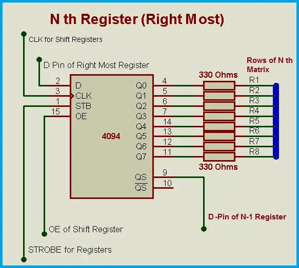
The IC 4094 (MC14094) is a serial IN and Parallel Out register with an option to cascade. The serial data sent by the microcontroller is loaded at the parallel outputs of the shift register. The strobe input loads the data into the individual registers. The output data is available at the output pins of the register, if the Output Enable is HIGH. The parallel outputs of each shift register are connected to the rows of respective 8X8 Matrix. The number of shift registers required is equal to the number of 8X8 Matrices.
Framing the rows data array
The line of text to be displayed is fragmented into columns for the respective rows data. An array called ‘rowdata’ is declared for this purpose. This array stores the rows data for each column of the text to be displayed. When a column is enabled in the display, its corresponding rowdata is issued using this array.
The size of the array should be greater than or equal to the number of characters in the text (if 10 characters are there in the text, the number of columns is 10*6=60). In addition to this, the empty columns should be provided to start from right most column of the display. So, size of the array must be equal to these empty columns and the actual text. For a 16 display with 16 modules, the empty columns are 16*8=128. For a text with a maximum of 200 characters the size of the array = ((16*8)+(200*6))=1328. The RAM of the microcontroller limits the size of the variables. So, depending on the RAM size, the maximum characters of the text is limited.

The text to be displayed is written in the user-defined function called line(“ABC”); Here ‘ABC’ is the text to be displayed. All the characters are framed in 5-Columns. After 5-Columns an empty column is inserted as a space between two letters. If the width of the character is less than 5-Columns, then this empty column is not inserted separately. The framing function looks after this condition. For the actual display shown above, the row data is framed as shown below.
This framing is done until ‘null character’ is reached in the line(); function. If the scrolling mode is selected, then empty columns are inserted before starting the text. This is done because the text has to scroll from the extreme right side of the display. The number of empty columns is equal to the 8*(number of modules). This is one of the possible ways.
Standstill Message on LED Display Board
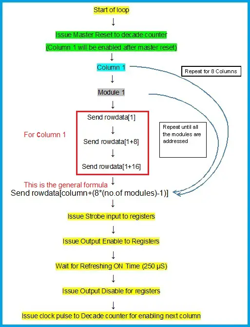
By now, we understood that the text is displayed column by column. So, in order to transmit the data from the microcontroller, we have to fragment the line of text into a one-dimensional array containing the rows data. In this mode, the length of the text is not considered. The text is framed into an array and the columns are enabled and row data is issued from the first column, no matter the text fits in the display or not. The variable called ‘scrolling’ is declared to decide whether standstill or scrolling mode is selected. If scrolling=0, then the standstill mode is selected. This can be initially defined in the program or can be changed in real-time through a slide-switch. After changing the mode, Reset input has to be applied to the microcontroller to frame the rowdata array. For a standstill display, the program flow is shown below. The continuous loop is shown here considering that rowdata framing has been completed.
Scrolling LED Sign
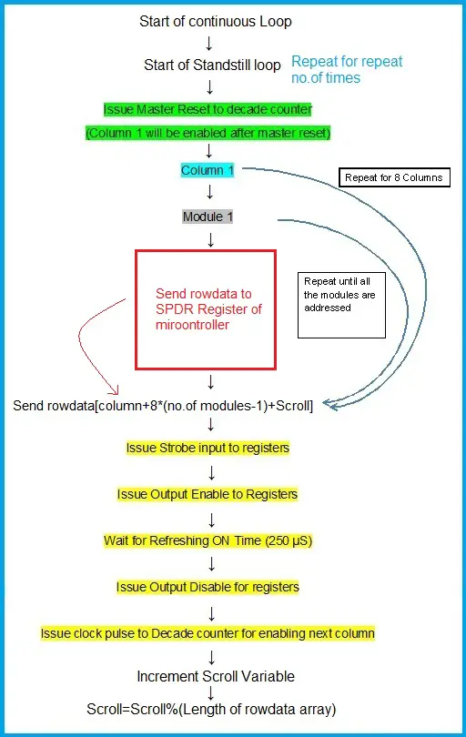
To scroll the text we will use a variable called ‘scroll’. This scroll variable is incremented each time after every column cycle. Once if all the columns of the display array are enabled and corresponding row data is issued then the column cycle completes. Thus the display array is refreshed with new data after every cycle. The speed of scrolling can be adjusted by increasing the number of column cycles before incrementing the ‘scroll’ variable. This scroll variable has the range from zero to length of the ‘rowdata’ array. If scrolling=1, then the scrolling mode is selected. This can be initially defined in the program or can be changed in real-time through a slide-switch. The speed of scrolling is decided by a variable called ‘repeat’. The standstill loop shown above is repeated for this ‘repeat’ number of times. If this value is more, then the scrolling speed is less. After repeating the standstill loop the variable scroll is incremented. This will change the array index of rowdata array pointed during the issue of serial data.
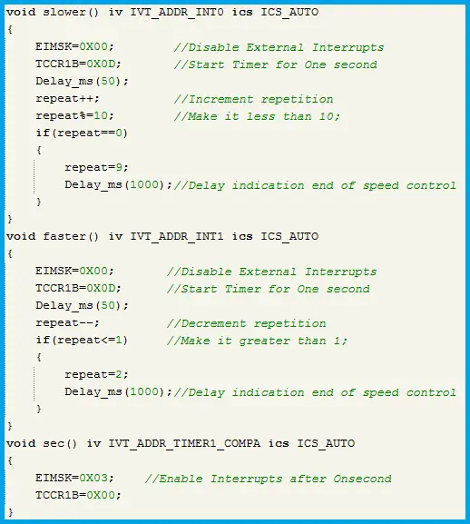
Changing the Scrolling Speed on LED Message Board
The speed of scrolling of electronic signs can be changed externally in real-time using push buttons. Two External Interrupts of the microcontroller are used for this purpose. One Interrupt INT0 is for decreasing the speed and another Interrupt INT1 is for increasing the speed. A variable called ‘repeat’ is used for controlling the speed of scrolling. This repeat variable varies the number of column cycles. If the slow button is pressed, INT1 is generated and repeat is incremented. Similarly, if the fast button is pressed, INT0 is generated and repeat is decremented. This value is used to define the speed. Thus, the speed of scrolling is varied in real-time.
The speed range is dependent on the length of the display array or the number of modules used. If the length of the display is large like for example, 5 feet long, then 4 letters/characters per second or 240 Letters Per Minute (LPM) can be used as a normal speed. This can be increased or decreased in real-time using speed control buttons.
Below is the program file of the display. The program is written for 16 Modules. If the number of modules is reduced to 8 or lesser, then the repeat loop should be multiplied with 10 instead of 5 for proper speeds. This is just to vary the speed or it can be ignored if the speed is satisfactory. There is c font verification function to see the characters one by one.
Download: LED Scrolling Display Board Program Code
1 Comment
Hi I’m unable to download the codes. Kindly let me know…