Description.
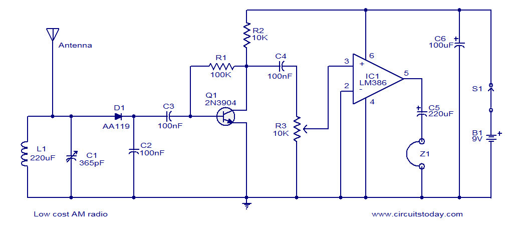
Here is the circuit diagram of a simple and low cost AM radio. The working of this radio circuit is straight forward. Inductor L1 and capacitor C1 forms the necessary tank circuit. Diode D1 performs the job of de-modulation. Transistor T1 is wired as a preamplifier whose output is further amplified by the IC LM386 to drive the head phone Z1. The 10K POT R3 can be used as a volume controller.
Circuit diagram.
Notes.
- The circuit can be powered from a 9V PP3 battery.
- Use a 100cm long metal wire as antenna.
- Experiment with the value of L1 for catching other bands.
- The circuit can be assembled on a Vero board.


24 Comments
Hi!
Which frequences can i recive with this thing?
Thanks!
It’s a great circuit. Works just fine, from the first try. My inductor (L1) was with about 120 turns of 0.3 mm wire around toilet papers’ cardboard. Signal was weak, but improved somehow when I have found better ground 🙂 Maybe one more curiosity is about preamp step, I have used 2N3904 transistor, but for a sake of science and curiosity, I have replaced him with Darlington BC517 (that one was extremely suitable because BC517 has identical pinout as 2n3904 npn 1-colector, 2-base, 3-emiter). of course, sound was extremely amplified, but as you probably guessed, the noise was also extremely amped, but it was fun experiment.
One more thing was crucial, I have used germanium diode OA90.
I tried building this three times and it doesn’t seem to work for me. The only things i did different is i have a small speaker instead of head phones. i am using two 110u Henrys coils in series and i am using a LED instead of the aa119 diode. any suggestions? I am doing this for a school project for my industrial electronics class in college.
you have to use high impedance head phone or 16 ohms speaker and for detector diode you have to use germanium diode only even silicon diodes will not work.
“Transistor T1 is wired as a preamplifier whose output is further amplified by the IC LM386 to drive the head phone Z1.”
Does Q1(T1) and R1 deal with the Noise or is it a pre-amplifier?
I could not understand half the electonics being taught at University.
printing error:220uH not 220uf
You are correct it should be 220uH. You can wind this also on a 10mm aircore former or on a pvc conduit 70 to 90 turns of 32 SWG wire or Litz wire.
as for Q1 is concerned it is a pre-amplifier to suitably raise the detected audio signal to have sufficient volume from the IC amplifier.
Hi Gustav D1 C2 acts as a De-modulator for RF and C3 is for coupling the audio signal to base of Q1 (you can also call it as DC blocking for base bias of Q1)
CIRCUS= CIRCUITS Sorry for the Misteaks!!
I LIKE RADIO CIRCUS!!
What’s the purpose f C2 and C3?
Hi Dedi No it has to be germanium point contact so that it can detect very low level signal also, its junction capacitance also will be low, the requirement. you can try OA95, OA85, IN34A OA70, OA79 etc.
can i change D1 (AA119) with IN4001 or IN 4002 ?
can this circuit drive an ordinary speaker?.
which type of inductor can be used in this circuit?. can i make an air core inductor or ferrite. please specify the number of turns for the coil also.
@ Mubarak
Try this link – https://www.circuitstoday.com/how-to-make-an-air-core-inductor
can you specify how much turns are required to make 220 uh inductor on ferrite ??