Description.
Many low pass filter circuits for subwoofer are given here and this is just another one. The circuit given here is based on the opamp TL062 from ST Micro electronics. TL062 is a dual high input impedance J-FET opamp which has very low power consumption and high slew rate. The opamp has excellent audio characteristics and is very suitable for this circuit.
Out of the two opamps inside TLC062, first one is wired as the mixer cum pre amplifier stage. The left and right channel are connected to the inverting input of IC1a for mixing. The gain of first stage can be adjusted using POT R3.The output of the first stage is connected to the input of second stage through the filter network comprising of components R5,R6,R7,R8,C4 and C5. The second opamp (IC1b) serves as a buffer and the filtered output is available at the pin 7 of the TLC062.
Circuit diagram.

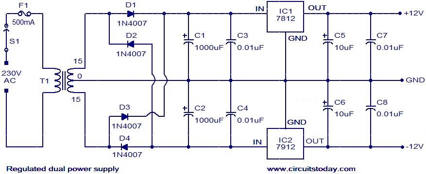
Power supply for the circuit.
Notes.
- Assemble the circuit on a good quality PCB.
- The circuit can be powered from a +12/-12 V DC dual power supply.
- IC1 must be mounted on a holder.
72 Comments
can i use another power supply circuit for this circuit ?
Hi, Need help here. what is IC1a and IC1b. Are these the different pins of same IC?
what is the IC numbers
yes..they r from same IC’s..it’s TL062
hello, myself Subham Chatterjee, can you please brief me what is function of the two POT: R6,R7
and pls say me may I able to give the out put to a 4″ subwoofer??
what is the frequency range of this filter circuit ?
good day sir! im just wondering if i can supply this circuit with +/-18 volts. hope you can give some advice..
No maximum limit is plus minus 15volt is safe to operate.
sir, can i use ic 4558 to built a low pass filter plz plz.. help
Sir,
I am new in electronic field. I want to build a subwoofer amp. I made a 150w poweramp for subwoofer using +35/-35v 5amp dual power supplay. Now i have a doubt. If any problem can i connect the filter circut to the 35v 5amp dual power supplay? Please clear my doubt sir. And give me a solution to overcome this limitation. Iam hoping ur replay. Please help me… Have a good day..
dis works wonderfully great wit my 100watt amp 10x sir 4 dis wonderfull job
Sir, may I know why the ceramic capacitors in the filter diagram have polarity symbols?
pls sir can I use electrolytic capacitor for c4 and c5??
All should be ceramic disc rated for 25volts or better
hello sir i wan’a surrounding circuit that means left right that to centre(mid range) and surround left right circuit
GIVE A USB MODEM CIRCUIT 3G/4G, FOR LOW NETWORK AREAS.
WITH DUAL, QUAD BAND ANTENNAS.
sir I built both 100 watt subwoofer amplifier and subwoofer filter but nothing works. I built subwoofer filter using 47k fixed resistor instead of pot and I connected to a sterio amplifier (I don’t know power of amplifier) but nothing come out please help in building both circuits I spend nearly Rs. 2000/- for this circuit’s component. thankyou.
Hello sir, this circuit oprate on 12-12 G.But i need it work on 12 0. Is this possble, if yes then how please help me
send an email (seethasub@hotmail.com)to me i will send the modified circuit
can some one please tell me the function of R6 and R7 and if i could use 2 presets and furthermore can i use a preset for R3 to make rare adjustments?
Hi for R3 you can use a preset as it is meant level, if you are going to use only the same input source always. R6 & R7 should be a ganged pot or you can use 2 identical presets adjust them in similar fasion such that they operate like a ganged control. you can attach both the presets with a thin non conductive shaft.
Sir can I connect this filter output to a 50watt power amplifire or there is any specific amplifire for this circuit please reply me.
Sir,maybe you have a layout pcb this filter,please send to my mail,,actualy I confuse conect pins pot line..
Thanks very much….
Hi rujtam go through following link for pcb layout etc
http://iq-technologies.net/projects/audio/008/
Thank u sir,,hope nice day…:)
The PCB shown in the link alone I have used. Philips single (for level) & stereo (for shifting the cut off frequency) PCB type controls will suit the PCB and layout. No need to wire Pots as they are connected through copper prints.
Sir,,I tes this filter,I connect out to subwoofer,but I can hear a sound,what the problem,or I must conect that to power amplifier..
Thanks sir,,I am newbie…:)
you have to connect the output of this filter to a subwoofer power amplifier of not less than 40watts RMS
Hi sir,,can I change R3 with 50k and R6/7 with 20k??coz difficult look for that pot..
You can use R3 50K and R6 & R7 20K ganged pot (called as stereo control pot).
sir im an enthusiast bout electronics .favor please sir please do mail me tthe more detail schematic of this low pass filter sir? with the values of each capacitors and resistors used? it means a lot to me sir if you grant my asked favor.thank you in advance
Hello Sir,
I am planning to build this circuit but I am not able to find this tl062 ic. so can I use tl074 instead of tl062.
YTou can use TL072 or TL082 they are dual Fet opamps. TL074 is quad you can use them also. Two of the quad can be used
Hi, i made this filter and it works perfect! I’m really happy with that. But i had to change R1 and R2 in to lower nominal couse it plays very quietly. I change to 4.7kOhm and than everything worked fine. Thank you! 🙂
P.S I was using my cell phone to test this filter.
thank u sir? i’ve done it the sound very low? ur the best?more power to u! im using ic op amp.4558?
Thankl u very much! i realy like this circuit the sound very deep? very low? thank u sir?
whats that largest subwoofer that could be powerd by this circuit 100W 200W 500W?????
sir, i want a great circuit for an 100 watts subwoofer amplifier. so please help me!
sir also how can I fabricate it on a copper clad board?????
I mean from where I can get its board layout
Sir Iam not able to understand the working of the circuit
please explain how this circuit work..
Hi Pankaj IC1a is used as a gain controlled buffer amplifier. IC1b is used as an active tunable low pass filter in the very low audio frequency area(with R6 & R7 filter charesterestic can changed a little.
You can use an universal board (staight line vero boards or connecting perforated dotted boards suitably)
i want dts 5.1 AV For home theatre demonstration my mail id
kaudios.s@gmail.com
sir i want dts 5.1 music for home theater demonstration where it available
Dear sir,
I would like to ask you if this filter can be used to infrasound frequencies … 1 to 12 Hz
thank you
two input signal left and right will be feed to this amp. and the output will become one??
sir is my understanding is correct that i will feed left and right signal in the input of the circuit, and later it will become one output…
what is the wattage of resistor?
do you have simple transistorized low pass filter? kindly send me if you have one because IC is kinda expensive thanks…
what is the wattage of resistor and voltage rating of capacitor?
Hi Alam through an 100K volume control you can feed the output of this filter to any high power amplifier.
Hi Abhinash you have to connect the output through high power amplifier to the speaker (sub woofer)
how to use this circuit with 150 watt amplifier ???
1) by connecting its output to the inputs of amplifier
or if it should be connected by other method so please define it …
it is really working and bass is too good.
thanks!!!
Sir, shall i connect the output of above circuit directly to speaker or i have to connect a TDA7240A amplifier to it???
Thanx in advance???
i assembled 100 Watt sub woofer amplifier. but it somke
please do needful
used spare
==========
24-0-24 transformer 5 ams
thank you
k.arunkumar
i assembled 100 Watt sub woofer amplifier. but it somke
please do needful
used spare
==========
24-0-24 fransformer 5 ams
thank you
k.arunkumar
thanks seetharamam the circuit works great but im not able to get which potentiometer to use for what
common man, need help !!! I saw this Circuit on the web which i
was searching for kind of one
for a long time and unfortunetly there
are some mismatch between PCB,
Data Sheet, Built PHOTO posted. i really
need this circuit so, looking for help from you to understand the
Circuit and need its working
DIagram http://www.free-circuit.com/
subwoofer-filter-gainer-auto-power-
system-circuit/
and also IC pins not numbered Mr.seetharaman my mail is Sevinfurly@gmail.com please post corrected Datasheet to my mail
I saw this Circuit on the web which i was searching for kind of one
for a long time and unfortunetly there are some mismatch between PCB,
Data Sheet, Built PHOTO posted. i really need this circuit so, looking
for help from you to understand the Circuit and need its working
DIagram
http://www.free-circuit.com/subwoofer-filter-gainer-auto-power-system-circuit/
can IcTLO62 be substituted with ICJRC4588
Hi Vivek it will work. the transformer should be rated for at least 12volts at 3amps
Thanks Seetharaman, for that website. I am working on this circuit and planning to connect it to a TDA 2030 audio amplifier im having will it work or do i need any other amplifier? Thanks in advance.
thanks seetharaman for the reply and can you help me in getting dual power supply from single output transformer.
thanks in advance
Hi Vivek you can limit the upper frequency response from 30Hz to 150 Hz by the turn of the ganged potentiometer (stereo potentiometer).
hi, can the frequency drop down 60hz?
Hi Mujtaba these ICs are with bipolar inputs hence input impedance will be low and may load the filter circuit. It is recommended to use FET input operation amplifiers for these filter circuits.
hi,
can i used 4558 or LM358 op amp replace TL062 op amp?
Thanks
Hi Mike NE5532 can be used as it works down to 6 volts(+3 & -3 volts).
Hi Romesh it is between 60 and 160 Hz as per pot setting.
Hi, nice post. By the way what’s the cut off frequency? Or can we change it using the 22k pot. Thanks in advance.
Hi seetharaman…..can i use NE5532 op-amp instead of TLC06?????
Thank u Seetharaman sir.
Hi Rupjyoti you can use TL072 or TL082
TL062 confirms to Military specification can work down to 4volt ( +2 & -2)
TL072 confirms to Industrial specification can work down to 7volt ( +3.5 & -3.5)
TL082 confirms to General Purpose use can work down to 12volt ( +6 & -6)hence for our use this is quite satisfactory
sir,
Can I use tl072 in place tl062.