Description.
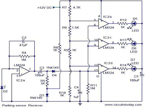
This simple circuit can be used as an aid for sensing the distance between the rear bumper of the car and any obstacle behind the car. The distance can be understood from the combination of the LEDs (D5 to D7) glowing. At 25cm D7 will glow, at 20 cm D7&D6 will glow and at 5cm D7, D6 and D5 will glow. When the obstacle is beyond 25 cm none of the above LEDs will glow.
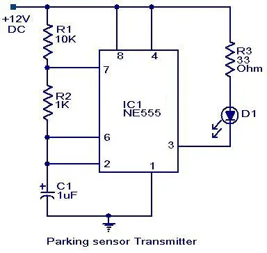
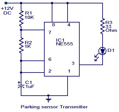
Two ICs are used in the circuit. The IC1 (NE555) is wired as an astable multivibrator for driving the IR Diode D1 to emit IR pulses. The operating frequency of the transmitter is set to be 120Hz.The IR pulses transmitted by D1 will be reflected by the obstacle and received by the D2 (IR photo diode).The received signal will be amplified by IC2a.The peak of the amplified signal will be detected by the diode D4 and capacitor C4.R5 and R6 compensates the forward voltage drop of D4.The output voltage of the peak detector will be proportional to the distance between car’s bumper and obstacle. The output of peak detector is given to the inputs of the other three comparators IC2b,IC2c and IC2d inside the IC2 (LM324).The comparators switch the status LEDs according to the input voltage their inverting inputs and reference voltages at their non inverting inputs. Resistances R7 to R10 are used to set the reference voltages for the comparators.
Circuit diagram with Parts list.
Notes.
- Assemble the circuit on a good quality PCB or common board.
- The D1 & D2 must be mounted close (~2cm) to each other, looking in same direction.
- The D1 can be a general purpose IR LED.
- The D2 can be general purpose IR photo diode with sun filter.
- The transmitter as well as receiver can be powered from the car battery.
- For proper working of the circuit, some trial and error is needed with the position of D1 and D2 on the dash board.
- All capacitors must be rated 25V.
- The ICs must be mounted on holders.
152 Comments
What should be distance between transmitter and receiver?
Can someone please tell me the excact function of the next componnents in the circuit above
–> C3, D3, C4, R11, C5, R8
not @ ol working properly.. though in breadboard we got partial output but in PCB we r Nt Ewn getting transmitter output!!!!
Mr.sitaram can u plz snd us the PCB design
v didn’t get d o/p for this circuit…
Hi I bought aftermarket car parking sensor device
http://www.amazon.co.uk/CAR-Reverse-Parking-Display-Sensors/dp/B011K4PFW2
I install in front bumper. Too much noisy. I plan to reduce rage from 2 meter distance to 1 meter distance . any help that I can do something on the circuit board
@hai – Since you have bought a manufactured product, its very hard to edit its program and reduce the distance to 1 meter. The option you have got is to build a customized circuit for yourself using a controller like 8051 or AVR or even Arduino and adjust the distance to suit yourself. But it highly depends on your skill in electronics and programming. Please be informed that you can’t edit the code inside your Amazon bought product!
I bought aftermarket parking sensor. i need to modify it from 2 meter distance to 30cm warning . I need to make buzzer speaker beeping only in red zone 30 -20cm and less. pls tell me what to do.
Note : I install parking sensor device on front car bumper . its continue beeping all d time all distance the range of device is 2 meter > I want reduce distance area to less than 40cm
PLEASE CAN I GET THE COMPLETE REPORT ON THIS PROJECT? I WOULD BE GRATEFUL IF I CAN HAVE IT. THANK YOU
Nice thish project and I am tri in use to my car
pls help when the power is on the three leds are glowing constanly and when all the resistors and reciver diode is removed again all the three diode is glowing what should i do pls help mee
Hai sir, I would like to do this project as my miniproject can i get more details
please send me the detailed connection for parking sensor circuit.
Hi sir,we doing this as our final year project…Need more information about PCB layout, requiring components and working…how to install it on a actual vechicle ….can you please send those details to my mail and it will very helpful for us…thank you
will 63v capacitors work?
Hello, Sir I m using things topic for my mini project but I have issue with the output can u please send me the full article?
Thankyou
hellow sir,should i use only a 12v source for it or shall i use 9v source….and i also have another prblm,once after connecting the receiver circuit all my LED glows,even when transmitter is swicthed off…what may be my prblm????
This circuit works perfectly with some modifications. However this circuit is not suitable for reverse parking because the IRs are reflected in Daylight if you adjust it for daytime then for night you have to adjust the sensitivity again. It will be better if you use ultrasonic Sensors.
Can u please tell me what changes u done to the circuit..
please do tell me about those modifications that made the circuit to work prefectly as I am also using the same circuit for my mini project…
Sir,
I have taken the above circuit for my mini project.
can u pls send me the details of the circuit with LED and Buzzer, it’s working and pcb schematics on my email.
My email is nglaiboon@hotmail.com
sir i’m doing this project at now.. i did not have 47pf. instead of 47pf what can i use?
Sir,
I have taken the above circuit for my mini project.
I hope that the circuit works…
can u please send me the details of the circuit, it’s working and pcb schematics..?
I badly need them…urgently
my mail id is as above
please send the details…
Hi Seetharaman,
I built the circuit on breadboard and discovered the the 555 timer had low current output to I had to amplify it using a transistor it did work, was wondering what you thoughts are about this?
Kind reagrds,
AA
Sir,
I have taken the above circuit for my mini project.
I hope that the circuit works…
can u please send me the details of the circuit, it’s working and pcb schematics..?
I badly need them…urgently
my mail id is as above
please send the details…
Yes you can mount ensure the sensors are isolated properly. Transmitter and receiver can be at either extreme of the PCB such that they do not interact in the PCB itself. Take care in the layout.
does the transmitter and receiver should be mounted on same pcb????
can u pls send me PCB schematics on my email pls its urgent
my email id is hemantgillurkar@gmail.com
Sir this circuit is great concept wise but i m new to these aspects…i have made simple portable mobile chargers but this circuit seems complicated but i want it to be done the best…
sir,
I am new in this field its very hard to fix components in breadboard referring the above circuit.
so pls can u help me
a video would also be very helpful.
any ideas how i could change the circuit to be as i want it !! reply as soon as possible plz!!
thanks alot in advance…..
please let me know if there is any circuit which will produce a warning tone inside the car when the car speeds to 100km/h.
Thanks
-aSHu.
Dear Mr.Sitharaman,
Your design circuit is responding well if it is properly installed
in a car. I also installed D1,D2 on front bumper with few modifications
as it is use-full during heavy rush hours in a country like India.
All the Best.
Farokh Kavas or anybody else(who tried this circuit),
I am bit confused with the mounting of transmitter circuit and receiver circuit. How they both will connect to each other and which ports or pins to connect. As per understanding, Transmitter will be installed on front or rear bumper and the receiver circuit should be installed somewhere inside car – on dashboard to be visible to driver.
Please help (URGENT).
Best!!!
can u pls send me compound list on my email pls its urgent
my email id is jjjaisonjoseph@gmail.com
sir,
could you plss send me the layout and all the neccessary details.. this would be my firt project and i want it to be the best.. but problem is that i am raw and i dont knw much about the things.. i will be vry thankfull if you could be a help..
sir this circuit dose not work properly…i have problem in transnetter and reaciver diode..how they working???
can tha part 2 of this circuit is cinnected with car???
Hi hussain go through the following link for clarifications.
http://www.redcircuits.com/Page40.htm
Hi Mr Seetharaman,
This circuit does not work well.
I designed the PCB mounted and assembled it. Emitter section generates a signal but is not detected at the input of Receiver section so the unit does not operate as expected. If you want more info you can email me kosmosxxxx@gmail.com
Kind regards
sir,
I am new in this field its very hard to fix components in breadboard referring the above circuit.
So pls can u help me
A video would also be very helpful.
Any ideas how I could change the circuit to be as i want it !! reply as soon as possible plz!!
Thanks alot in advance…..
I’ve set out this circuit on Eagle CAD, I tested it and it works 100%
If anyone wants the layout replay whit your email address
I made two, one with LED’s and another with a Pizo buzzer.
This is possible because of Seetharaman,
Brandon Cooper
could you please send me the PCB schematics?
is it possible to combine both led and buzzer? and can you send me the the layout, thank you.
and can you tell me what IR diodes to use because i dont know what diodes to use
Hi can you send me the PCB board schematics, I have built this circuit on PCB using circuit wizard, i have built the circuit and it is completely unresponsive! PLease send ur schematics
Send me PCB layout please
Send me please your pcb of this circuit….
Best regards
To the attention of Mr Cooper and Mr Seetharaman
Dear Sirs,
I have read your article on the IR Parking Sensor and found it very useful and interesting, could you please send me the PCB schematics?
I would like both LED and Buzzer.
my email address is shown above
Kind regards
A. Gonzalez
Mr Cooper please send me PCB design of this parking sensor
plss send me the layout.. i will be thankfull….
I in need of the layout could u please send it to me….
sorry I am in real need….please send it quickly..thanks
can u plese send the entire details of this project
could you plzzsend me the pcb schematics
Can u pls mail me the layout? i wud b very much thankful
please help me regarding this project i choose this for my final project, but i am not clear about it please send me layout with both LED’s and buzzer
Hi,
can you please send me the layout.
Thank you.
plzz send me the schematics and pcb tracks layout
Pls can you kindly sent me the layout because I have already assembled the ci rcuit but it is not working properly as it should be. Thank you
sir,could u plz send me the layout of this circuit using LED
sir please send me the layout
sir there is on problem i have connected it on bread board but all three leds are glowing even though ir transmitter and receiver are removed
please send me modified schematic diagram of it, because when i made connections all LEDs are glowing even when receiver is removed.
thanks for sharing your ideas.
sir as you said that the electronics are kept in the car driver panel.. means only ir transmitter and ir receiver is mounted on rear bumper, and all other circuitary is in driver panel… is it so???
yes you are correct.
okay… thank you sir…
can you send pcb schematics of this circuit or can you give your email id.. so that i can show you how i made that.. n m still wondering that it is not working properly…:(…
sir as you said that the electronics are kept in the car driver panel.. means only ir transmitter and ir receiver is mounted on rear bumper, and all other circuitary is in driver panel… is it so???
Reply
as the IR photodetector use is not detecting the signal our project is not working properly.wht would b d possible ways to done it?n tell me one thing that the obstacle should some reflective surface like metal or mirror?
Hai Swara IR transmitter and receiver should be as close as possible(side by side) ensure they matched and they are responding by directly facing each other. if these things are ok. ensure the reflecting surface is not dark it should be bright preferably white. please go through the following link.
http://www.clear.rice.edu/elec201/Book/assembly.html#SECTION00864000000000000000
sir can u please send the total working detail of this circuit?? its urgent…
i have made this circuit on pcb.. but i dont know why, it is not working…..:(
Hi happy this works on the received Infrared signal level. The parking sensor transmitter transmits the IR signal which is received, while some close obstacle reflects back the IR signal. The receiver receives as per the signal level received the LEDs glow. Closer the obstacle all the LEds D5, D6, D7 will glow. As the obstacle is moving away little D5 will extinguish if moves away further D6 also will extinguish if it moves further all the will extinguish. Both the transmitters and receiver sensors are mounted on the rear bumper. The electronics are kept in the car drivers panel and can be energised by the car battery when the car is reversing.
sir as you said that the electronics are kept in the car driver panel.. means only ir transmitter and ir receiver is mounted on rear bumper, and all other circuitary is in driver panel… is it so???
sir what about other electronics?????? there are only transmitter and receiver circuits…
How would i be able to increase the range of the IR LED or the photo diode so i could detect obstacles at something like 50cm?
my back up sensor fails whe my trailer harness is installed, harness not in use, but after a time the sensor fails to operate when i unhook the trailer harnes the sensor wil work any suggestions
sir, can you please send me the following about the parking sensor circuit???
pcb layout
circuit schematics
block diagram
component specifications
i will be very thankful as i require this for my final year project.
hehe, sorry forgot to mention this.
laser light is coherent, so as for only a single small dot being reflected back, so maybe use some special concave type lens or something in front of laser, to better the chances that the photodiode can detect it.
This circuit I think will work, except for the viewing angle problems(ie setting it up), and further intensifying the exposure(IR)
But knowing the viewing angles, 60-120 or so degrees will work I believe.
But, what I`d rather do, is use the ir laser diode from a dvd burner, and use some driver circuitry for it, like the 555 used here, doing some modulation. I just believe the ir laser will be better equipped as for intensity.
Well, just my thoughts.
for what frequency does the transmitter-reciever work? is there a way by which the reciever can be tested?
it is good circuit, but i would like to know how to install is on actual vehicle ? i hope u will satisfied me with a proper answer
sir
this ckt not work in proper way pls solution for me
what if i placed the parking circuit at a point in rear bumper of my car & on parking there is a pole behind my car, not in alingnment of the LEDs, than the circuit will not detect any obstacle…….so how can i use it on full width of my car…..plz ans on my email..
is there any reply for any of the questions in the comment , if so please post it it’ll be of great use . thank you
Sir,
a video would also be very helpful.
please mail me the required. my id is: ajib_smart@yahoo.com.my
Thank you.
Had anyone try out this circuit and work?
hi sir
i am a student in the lebanses university and i really wana know how to build this thing and put it on a gadget but plus i need instead of glowing on the last 5 mins i want it to change side or to just block in its place !! any ideas how i could change the circuit to be as i want it !! reply as soon as possible plz!!
please mail me the required—-> layal_ghossein@hotmail.com
thanks alot in advance
Hello,
can i know how can the transmitter and the receiver can be place? i have problem to place the two circuit together. besides, i want to know further details about this project. Please mail me the required –> sen92.capricorn@gmail.com
thank you.
Sir,
I’m a beginner and i want to know the more details on this project.Can i know how am i suppose build the receiver and transmitter? and a video would also be helpful to do this project.. Thanks.. please send me email about this project details.. –> sen92.capricorn@gmail.com
once again, thank you..
Sir,
a video would also be very helpful.
please mail me the required. my id is: tally_ho_27@yahoo.com
Thank you.
Sir,
Could you please mail me the details of the project? i am a beginner and was wondering how exactly do the leds respond to change in proximity of the obstacle. could you explain how to implement the above on a bread board? how am i supposed to place the transmitter and receiver. i tried building them separately on two different breadboards but the receiver doesn’t detect anythng. i shall be extremely grateful if you could help me out.
Thank you.
Hi Seetharaman,
Good day,
Just to follow up this request/inquiry dated Jan.24, 2012,
as quoted;
How can I determine the exact distance of the sensor,meaning; from the dashboard to the rear bumper and to any obstacle at the rear of the car.
From the sensor at the dashboard, and to the rear bumper of the car, how many centimeters total all in all?
Thanks .
Thanks a lot for the info…very good site!!
pls issue full details about the projects
pls send all details of the project .its a wonderful work.i too have many ideas but can’t impliment any ideas
cijoyworld@gmail.com
Hi Seetharaman,
How can I determine the exact distance of the sensor,meaning; from the dashboard to the rear bumper and to any obstacle at the rear of the car.
From the sensor at the dashboard, and to the rear bumper of the car, how many centimeters total all in all?
Thanks .
oic thanx seetharaman!
Hi Jason you need not be very specific about the frequency as this project only senses the level of IR signal received. Not compatible with Ultrasonic sensors you require modifications in both transmitter and receiver circuit.
can the diode replace with a ultrasonic sensor?
hi i m using this circuit as my school project but i cant get a 40khz pulse from the 555 timer n i change twice the 55 ic d still i dont get a stable 40khz pulse may i noe y?
hey this project required any programming part….,& please give me component list of this project please it’s urgent for me please……….
Sir,could you please send me also the block diagrams and all details of these project,appreciably with an audio buzzer instead of LED?
Thank you so much!
Everyone wants the audio version of the circuit. The mods needed are very simple. The buzzer can be driven from the 3 lm324 outputs as long as the buzzer current needs are not greater than the output of the lm324. Care must be taken not to over tax the output. Use different resistor sizes to change the ma of current to the buzzer. It will progressively get louder if you start with larger values and decrease the values as you go. Use Ohms law for resistor values. If needed, a transistor hooked from the output can drive larger milliamps to the buzzer. Some buzzers even have two inputs that can be driven. One that pulses and one that is steady. You could increase the sound then pulse when maximum range is reached. A little research and creativity will make the circuit do wonders. Good luck.
sir im nteristed about the circuit.can you send me similar this circuit to monitor the level of a mini dam or reservoir 30 meters high. equevalent to 30, LED monitor
Hi Testpen Mount the electronics in the car, place both the sensors as per notes.
The D1 & D2 must be mounted close (~2cm) to each other, looking in same direction.
The D1 can be a general purpose IR LED.
The D2 can be general purpose IR photo diode with sun filter.
The circuit will definitely work.
Hi! I had try your diagram but still don’t know how to get the true operation. Can you show me how to arrange the D1&D2? Can i use ultrasonic transducer?
sir,could you please send the details,block diagrams and all details of the sensor,appreciably with an audio buzzer instead of LED s,
Read more: https://www.circuitstoday.com/parking-sensor-circuit#ixzz1ND31hvIX
Under Creative Commons License: Attribution
this site is very good in others comparision but please help me i nee a circuit of wirless rc car with forward and backward 100feet rc range and high speed operated with 9vlt battery if you can do this i will say you excellent tag that circui in your website thankyou
Dear Sir,
Please send the shematic of the PARKING SSENSOR CIRCUIT
with an audio buzzer instead of LEDS.
Thanks in advance
Kriakos from Athens
can somebody plz send me the pcb layout of this project. my email fidz_ebai@yahoo.com.my
Hi. I would too like to have a full copy of this article.
i need a parts list too if u have one.
thanks.
email> lovro.jenko@gmail.com
have a nice day=> from Slovenia
please I need an advice for this project
sir,could you please send the details,block diagrams and all details of the sensor,appreciably with an audio buzzer instead of LED s,
thankyou for this project
want 2 knw the details of the circuit…why the value of the resistance is so chosen,capacitor etc
please give me small sensor circuit
it so tough for me as a student. . . . . do u have a simple circuit for the same. . . . .
sir admin..can i also have a full copy of this article..
its my project for may last subject..and i can’t finish it.
i can’t make it work.i’m confuse about the parts..like the sun filter,and photo diode..here’s my e-mail add. x0xo_x0xo@yahoo.com
-thank you so much sir admin.
Hi Monica it may cost you around INR300/- in India.
i have to make project on this topic…….
plz tell me about how much cost its make……..plz rply as soon as possible
Hi JoySankar, i have transferred energy using laser beam in one of my project, even we could communicate through it, i will search if i still had its diagram,
anywaz if u r intrstd cntct me Badeekh@yahoo.com
hey Peter Davidson, i got ur conserning one, reversing parking buzzer, but problem is that i cudnnt adjust its sensitivity, anyhow u can make it ur self, cntct at Badeekh@yahoo.com
Admin
i got the sheild from a scrap vcd… thx:-)
Hi Patience Karemera hope you are enjoying by assembling and using it successfully. try whenever possible the circuits appearing in Circuitstoday, they are all tested circuits you will find them useful and also will give immense happiness by the results after assembling them.
This circuit is interested because it have been appreciated by every one who has seen it AND i am happy to know it.
how long the way of transmitter can transmit???
hey, can anyone send the pcb layout of this project to me too? my email is wexiang88@hotmail.com. And by the way, can 7-segment replaced the LED( output )? hopefully i can get the answer asap =x
can somebody plz send me the pcb layout of this project. my email kmbeke@gmail.com
Hi has anyone designed a parking sensor for smalls cars(toys)? I needed for my demonstration at school.
hi, iam doing this project for my final year, could you plz send me the block diagram and any material concerning this project, i will be so grateful. my email is kmbeke@gmail.com
i am a student of EEE. pls describe the photo diode and the sun filter. pls i was choked up at that stage. and how does the transmiter work.
Hi Koech please send your email id for the full article.
could you please send me the following about aparking sensor:
circuit schematics
block diagram
component specifications
i will be very gratful as i require the same for my final year project
plz show full description and detail of every component
Can any1 pls design the same having an automatic braking system if d car reaches a specific distance near to d object????
thanks for your great articles. i will learn it
Hi Richa in my openion you cannot use a capacitor with lower voltage ones, rated voltage is good. higher voltage capacitors can be used sucessfully, but on the long run they may get dried up earlier than the rated ones.
we dont have the exact rated components like v capacitors are rated 63V.please reply me in my mail adress.
I am student of B.Tech Electronics and Communication Engineering student.We are making a project on Wireless Energy Tranfer. So if it possible on your part to provide us some information along with the circuit diagrams,please help us in making our project.Thanks
excellent write-up i would like to learn much more.|interesting, I am going to try this out and report back.
Any updates on the buzzer version of this?
Has anyone done it? I’m interested..
All
In case anybody missed it, this circuit activates LED’s instead of the customary audio buzzer that one is used to hearing in cars. And normally the closer you get to the obstacle the more persistant the buzzer becomes. This circuit activates an LED and then the longer the obstacle is present depends on when the 2nd LED swithes on and then the 3rd. Allthough this circuit will work I don’t think it is pratical for when somebody is reversing and looking into their mirrors. It needs conversion to audio.
Any updates on the buzzer version of this?
Has anyone done it? I’m interested..
can u give still more explanetion on this parking circuit sensor plzz.how can we check the output after assembling the circuit.
I am saurabhagrawal syudent of B.tech of electronics and communication.we are making a project on car parking sensor so please help us to making it………….thanks
as a sun filter can i use red cellophane paper
miniature sun filter sheets are available in the market. You can use a dark cellophane paper or a piece of X ray film for the purpose.
The best source to get a sun filter is your old VCR with remote. Most probably there will be a filter covering its IR sensor.
what will be the cost of this project?
can anyone please design the pcb if this circuit? i cant get over the connections my email is tushar0110@yahoo.co.in
At the moment I am not designing PCBs for readers. But I am seriously thinking on it.
You can easily design PCbs by yourself using softwares like PCB123, Eagle PCB etc.
can anyone please design the pcb if this circuit? i cant get over the connections
can i use phototransistor instaed of photodiode
@ Sydney Airport Parking
Thanks for notifying about the situations in Australia!
could you design a reversing Parking sensor circuit with a buzzer/alrm whennear object. it is for a school project i have to do for very soon.
thanks
Parking is a problem at airports and in Australia the airports are owned by the Airport Corporation. They effectively have a monopoly on parking at the airport. What some enterprising individuals have done is sell parking spaces close to the airport and offer a free shuttle service to the terminal. This can be very cost effective and is really taking off in Australia.
plz someone give me a circuit diagram of mini project which consist of JFET or MOSFET……..
Aziz ahmed
would you plz help me to do the project report of this topic
can you mail it?