Description.
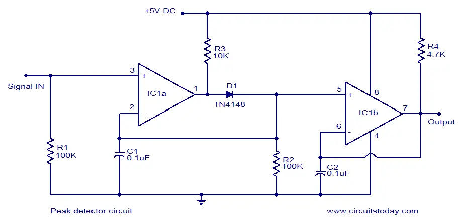
This is the circuit diagram of a very simple and cheap peak detector circuit. This circuit operates from 5V DC and can detect signals up to 150 KHz. Dual comparator IC LM393 is the heart of this circuit. First comparator IC1a is used for detecting the peak of the input signal. Second comparator IC1b is wired as a buffer to increase the current gain.
Circuit diagram.
Notes.
- The circuit can be assembled on a Vero board.
- The IC must be mounted on a holder.
- Use 5V DC for powering the circuit.
- The input AC voltage should not exceed 10V peak to peak.
- The input sensitivity is 10mV peak to peak.


2 Comments
Good day,
I understand this is an old article, nevertheless I tried the circuit and I have been successful with the LM393, however the precision goes down the drain past 1.5 Vpp, even at low frequencies.
I’ve also tried with a LM339, but it simply doesn’t work.
Would it be possible to present an example with values/oscilloscope screenshots at some crucial test points.
That would be greatly appreciated, allowing me to counter verify the circuit I made and determine where I made an error. I revised my circuits many times, but still can get it work over 1.5 Vpp with a 393 and not at all with a 339.
Regards.
Update :
I finally got it working with the quad comparator. There was a “cold” solder on the board. Nevertheless, the input signal can’t exceed 1.5Vpp in order to have a valid output signal. Perhaps I would need to modify the input resistor, but I guess the debugging process is in my court.
If by any chance someone came up with a “fix”, it would be nice to share.
Regards.