Proteus is a simulation and design software tool developed by Labcenter Electronics for Electrical
and Electronic circuit design. It also possess 2D CAD drawing feature. It deserves to bear the tagline “From concept to completion”.
About Proteus
It is a software suite containing schematic, simulation as well as PCB designing.
- ISIS is the software used to draw schematics and simulate the circuits in real time.The simulation allows human access during run time,thus providing real time simulation.
- ARES is used for PCB designing.It has the feature of viewing output in 3D view of the designed PCB along with components.
- The designer can also develop 2D drawings for the product.
Features
ISIS has wide range of components in its library. It has sources, signal generators, measurement and analysis tools like oscilloscope, voltmeter, ammeter etc., probes for real time monitoring of the parameters of the circuit, switches, displays, loads like motors and lamps, discrete components like resistors, capacitors, inductors, transformers, digital and analog Integrated circuits, semi-conductor switches, relays, microcontrollers, processors, sensors etc.
ARES offers PCB designing up to 14 inner layers, with surface mount and through hole packages. It is embedded with the foot prints of different category of components like ICs, transistors, headers, connectors and other discrete components. It offers Auto routing and manual routing options to the PCB Designer. The schematic drawn in the ISIS can be directly transferred ARES.
Starting New Design
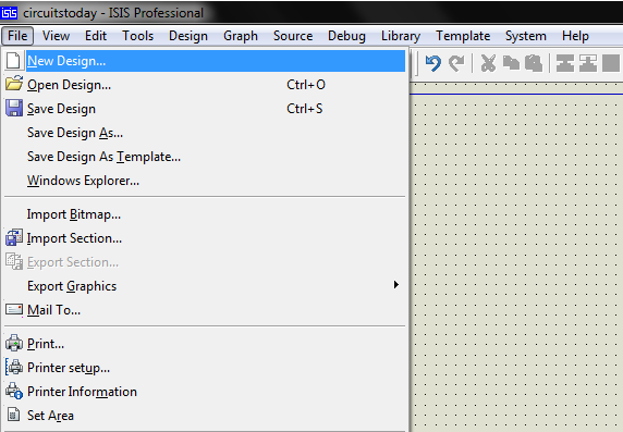
Step 1: Open ISIS software and select New design in File menu
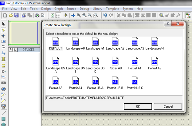
Step 2: A dialogue box appears to save the current design. However, we are creating a new design file so you can click Yes or No depending on the content of the present file. Then a Pop-Up appears asking to select the template. It is similar to selecting the paper size while printing. For now select default or according to the layout size of the circuit.
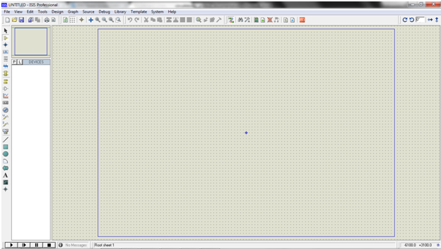
Step 3:An untitled design sheet will be opened, save it according to your wish,it is better to create a new folder for every layout as it generates other files supporting your design. However,it is not mandatory.
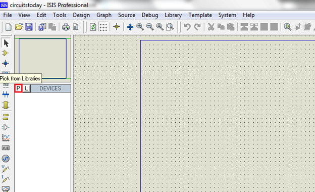
Step 4:To Select components, Click on the component mode button.
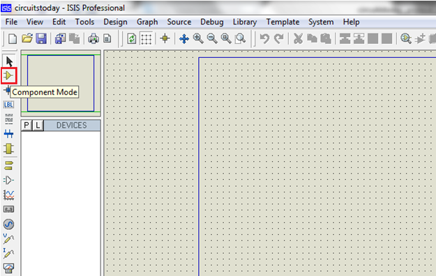
Component Mode
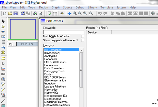
Step 5:Click On Pick from Libraries. It shows the categories of components available and a search option to enter the part name.
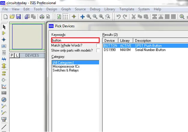
Step 6: Select the components from categories or type the part name in Keywords text box.
Example shows selection of push button. Select the components accordingly.
Step 7: The selected components will appear in the devices list. Select the component and place it in the design sheet by left-click.
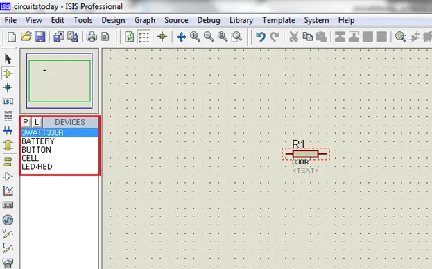
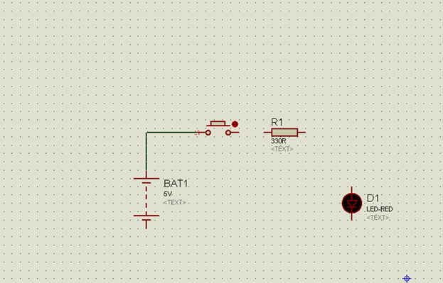
Place all the required components and route the wires i.e, make connections.
Either selection mode above the component mode or component mode allows to connect through wires. Left click from one terminal to other to make connection. Double right-click on the connected wire or the component to remove connection or the component respectively.
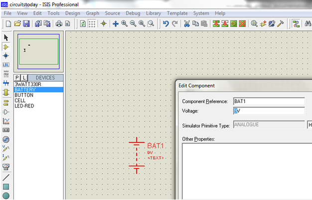
Double click on the component to edit the properties of the components and click on Ok.
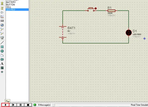
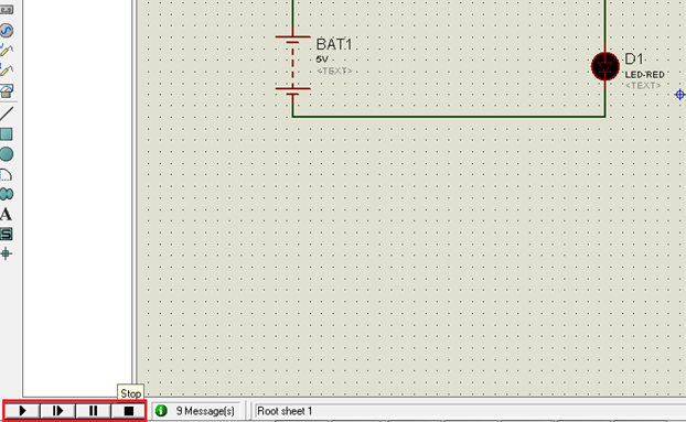
Step 8:After connecting the circuit,click on the play button to run the simulation.
In this example simulation, the button is depressed during simulation by clicking on it to make LED glow.
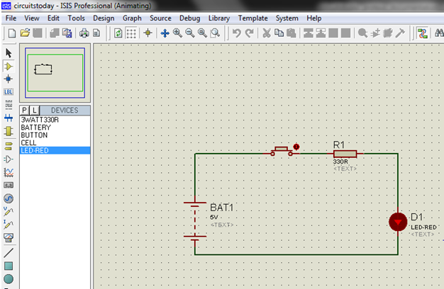
Simulation can be stepped, paused or stopped at any time.
Okay! That’s all enough for an introduction to Proteus Software! Now lets get to serious learning. Next chapter or the first serious chapter in this tutorial series is – Switches and Relays in Proteus. Read this chapter to learn how to work with different types of switches in Proteus.
Once you finish the chapter on Switches, go to the succeeding chapter – Tutorial on LED and Bar Graph Display with Proteus – which explains how to work with led’s and different types of LED’s in proteus.
11 Comments
comment triuver le composant bornier,car il n’existe pas sur mon logiciel proteus 7.7 SP2
I Use cd4049 for buffer circuit. The pin vdd and vss is hidden. How to connect the both pin to circuit.
Vdd and Vss are connected to +5V and GND by default in the simulation software.
If the circuit is being tested practically by using the actual components then, connect +5V to Vdd and GND or 0V to the Vss Pins.
I have a problem program that does not have the integrated circuit library that I need
I searched for libraries that included the integrated circuits I needed and installed them to a program library but did not work well show the program but I can not do experiments on them or analyze the circuit
my ic…..uc3842…45…34
i need to make dc to dc converter
12v to 35v
can you help me for that
Is there a link that includes these integrated circuits or a copy containing them
Sir/mam I have a small doubt
Why we are choosing Proteus for the simulation
Any simulation software is used to test the design and fix the bugs, hence Proteus. If you are asking why to choose Proteus, it provides simulation as well as PCB Designing.The simulated circuit can be directly converted to PCB Design.
Its work very nice example
Thanks for your comment, you can go through the next chapters for more examples under proteus category.
i want to use raspberry pi. can i use it?
i want this orginal software trail version…
to whom i have ti contact now..pls help me……
it is very nice