In this tutorial, we will be learning on how to use the “Switch” component in Proteus simulation software. In case you have not got on through the basics of Proteus, here is the link – Proteus PCB Design and Simulation Software – Introduction.
1.1 Basic Operation of a switch
A switch is component that is used to either make or break a circuit path. There are different types of Switches which can be operated
(i) Manually by mechanical input
(ii) Electrically by a control signal generated by control circuit
(iii) Combining electrical and mechanical components
1.2 Types of switches available in Proteus
Proteus provides switches of different categories and almost all the configurations that are being used in real time applications. Each type of switch has its own application, even though same operation is performed by other type of switches.
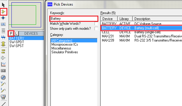
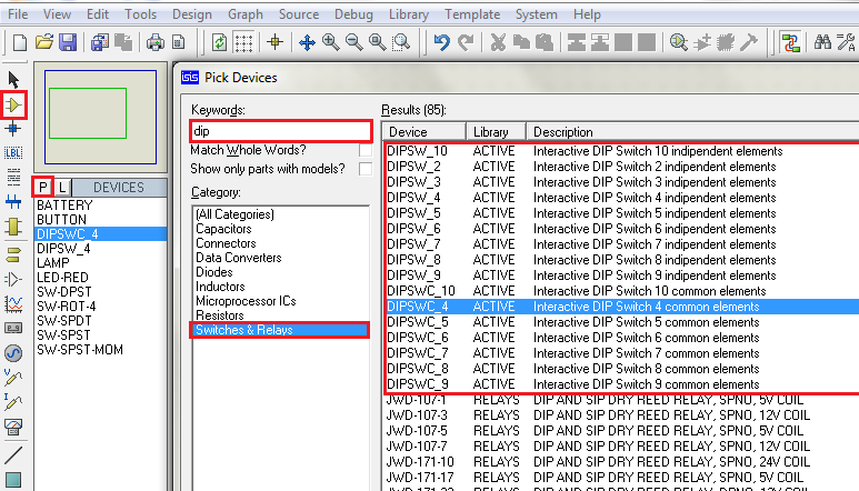
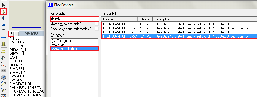
Switches can be found in proteus software under Library category “Switches and Relays”. Remember to select ‘ACTIVE’ components so that the simulator provides real time interface during Simulation.
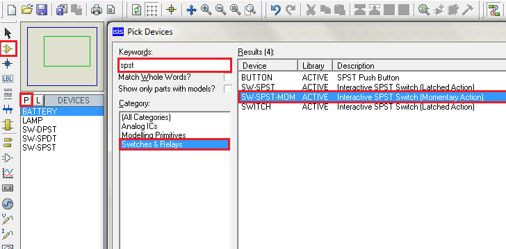
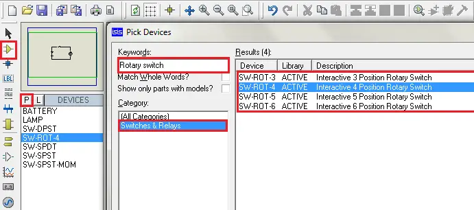
Step 1: Select component mode
Step 2: Click on Pick devices ‘P’ to select switches category from the library
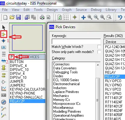
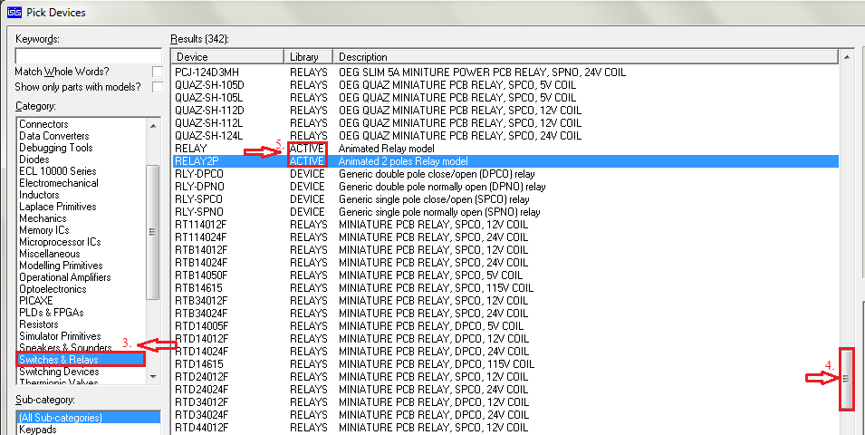
Step 3: Scroll down categories to find ‘Switches and Relays’. Select this category and it shows the available switches in the result.
Step 4: Scroll to find the required component according to circuit.
Step 5: Remember to select components with ACTIVE property under Library column of the search results for interactive simulation.
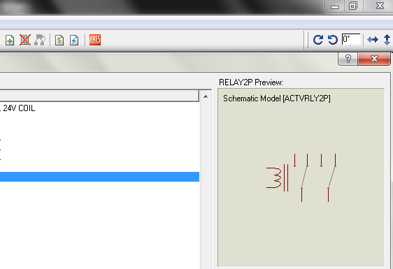
Search results show the preview of the component selected for instant reference.
Viewing in power rating point of view, basically switches can be classified as signal switches, used to give input to the control unit generally up to 24V DC with current of the order of 10 mA and power switches used to control the state of a load generally 115V AC, 230 V AC etc, depending on load requirement with current ranging from 100 mA to several Amps.
This chapter is dedicated to introduce the switches available in proteus and are explained through practical applications.
1.3 Switch board connections-House wiring
For controlling domestic loads
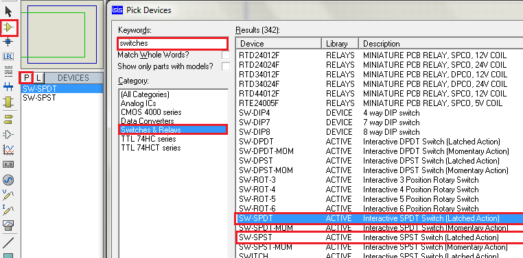
SPST: Single-Pole Single-Throw switches are used and for stair case light (load) control type.
SPDT: Single-Pole Double-Throw also called as Two way switches are used.
Applications in which two independent paths to be connected or disconnected by one point input uses:
DPST: Double-Pole Single-Throw type of switches, generally to separate both supply terminals from Load (Phase and Neutral in an AC Supply system) generally called as M.C.B
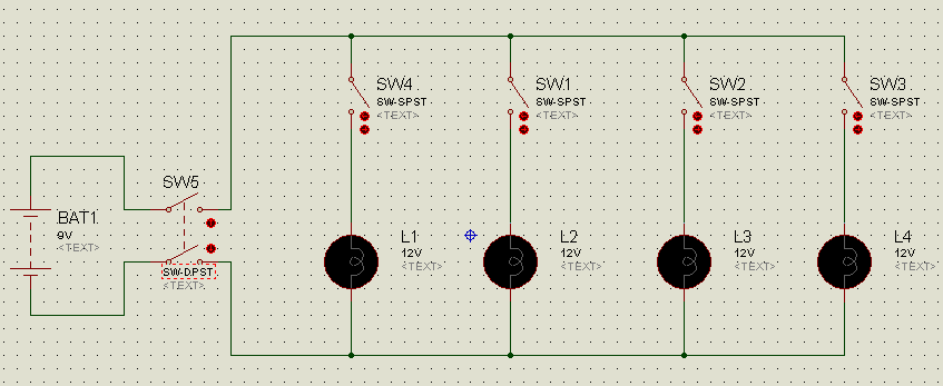
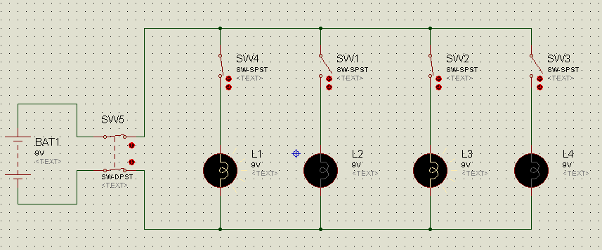
The simulation circuit shown here uses DC source to feed the lamp loads. However, same circuit is applicable for other voltage sources (Alternating Current Source).For beginners, this circuit can be safely connected and tested using a bread board to understand the operation of switches through hands-on experience.
For beginners who are trying to implement practically in homes, please take safety precautions and cross-check the conductor ampacity, load ratings, switch ratings that are used.
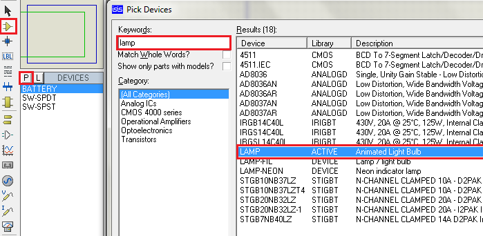
As described in section 1.2 select the switches mentioned above. Also select a Battery, Lamp from libraries ‘SOURCES’ and ‘Optoelectronics’ respectively.
Place the components in work space and connect the components as per circuit diagram. To have a review on how to connect components go through the creating a new design chapter. Right-click on the component and select the orientation of the component if required.
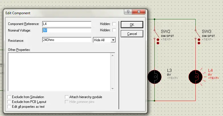
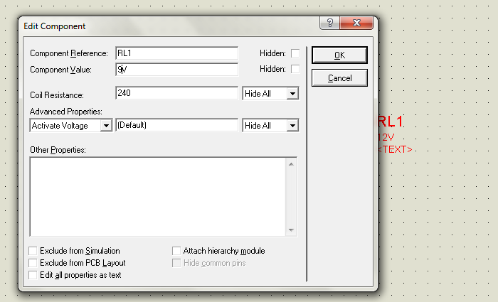
Double-click on the Lamp component and edit the voltage to 9V and click ‘OK’ as we are using 9V battery and it is easily available.
Now, check the connections and properties of the components and Run simulation by clicking on Play button at the bottom left. Operate the DPST by clicking on switch lever. Then close the load switches one-by-one and the lamps will glow.
1.4 Two-way switch connections
This kind of switches are mainly used in stair case lighting. Select a SPDT: Single-Pole Double-Throw switch in the way similar to SPST in above example. Connect the circuit as per the diagram.
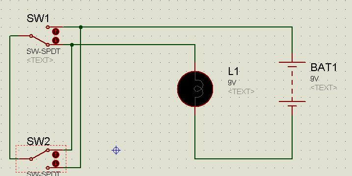
Change the voltage property of Lamp to 9V and run the simulation .Operate either of the switches to toggle the state of the lamp irrespective of the state of other switch. The lamp toggles from its state thus providing option to control the light from different floors.
Simulation of Stair case lighting
1.5 Latched and momentary action of switches
Just like Doorbell switches push to ON type of switches are available in Proteus. In domestic applications they are used as doorbell switches, whereas in industries they are used as Start and Stop switches in various control panel wirings like relay latching, for example a Motor starter. These switches are in ‘Switches and Relays’ library with a description of Momentary Action.
Connect the circuit as per the diagram and run the simulation. Operate the switch for the bulb to glow and release to OFF the bulb.
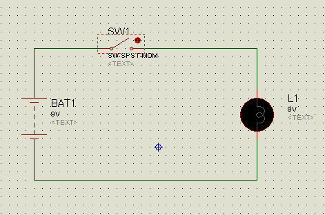
Simulation of Momentary Action switch example.
1.6 Rotary Switches
Fan speed regulators and frequency tuning circuits use rotary switches. They provide provision for common terminal to connect with more than one terminal independently.
This circuit shows basic operation of rotary switch even though it has different applications. To explain with the topics covered so far connect the circuit as per the diagram and operate the switch.
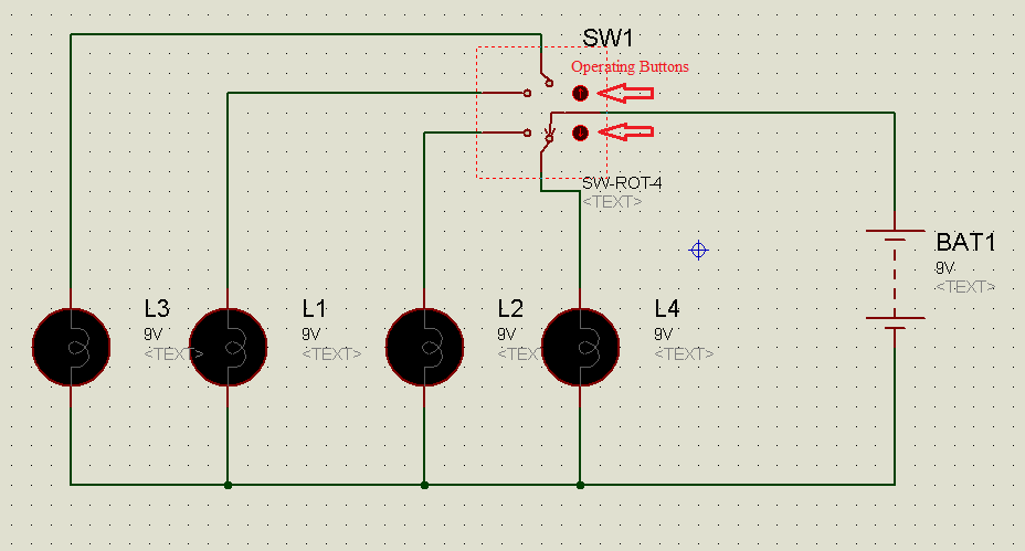
Simulation of Rotary switch example.
1.7 Push Buttons
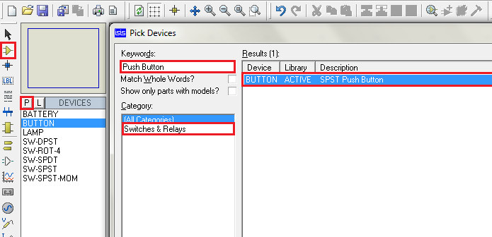
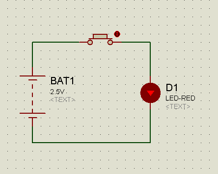
Human Machine Interface (HMI) control panels mostly use this type of push buttons. They are called as membrane switches. All the keypad type mobile phones also use membrane type push buttons. Digital clocks, watches, alarms, most of the electronic gadgets that provide Human Interface use this switches. To select this switch, type ‘Push Button ’in keywords. Also select active LED for this example. Connect the circuit as per the diagram and run the simulation. Operate the switch for the LED to glow.
1.8 DIP Sliding Switches
DIP stands for Dual In Line Package. This is a type of component package. These switches are generally used for selection of mode of operation of an equipment or selection of a process or control circuits which require variable reference inputs before they are powered ON or sometimes even after powering ON. They may not be operated frequently, so designed to embed in the control circuit to occupy less space.
Depending on reference input requirement they are available in two types.
(i)Common element
(ii)Independent Elements
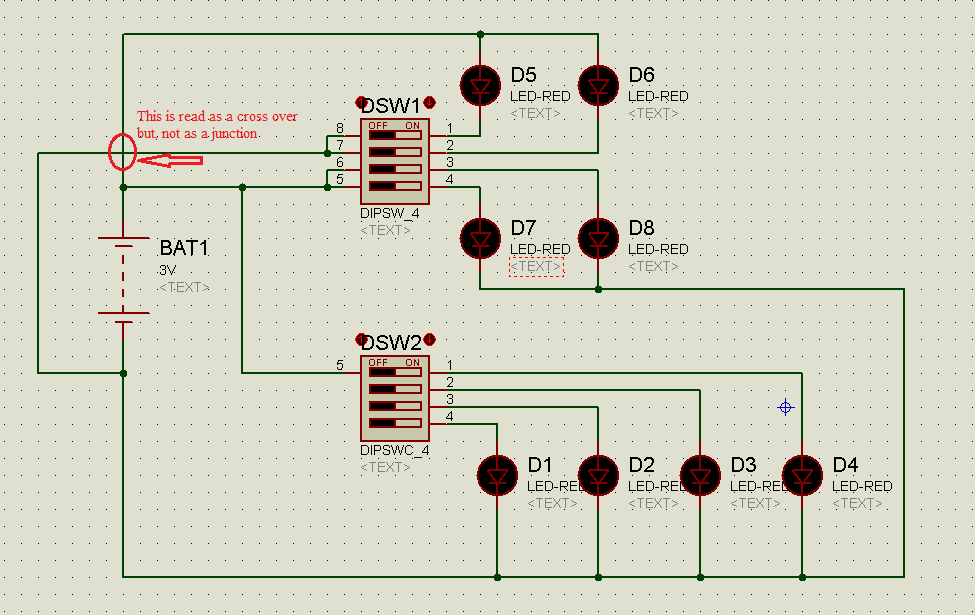
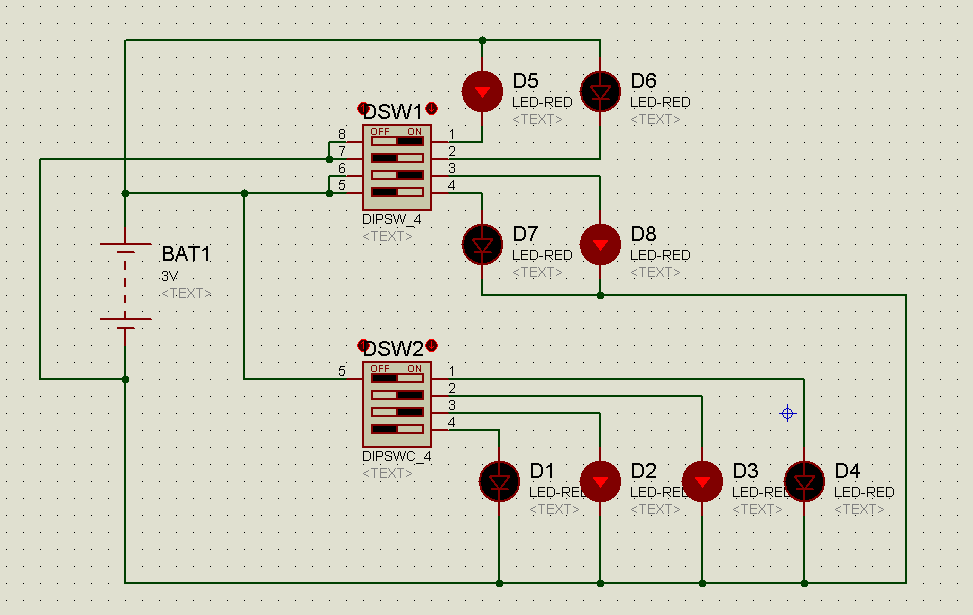
Connect the circuit as per the diagram and run the simulation.
DIP Switch 1 is independent element type.D5,D6 are common +Ve and D7,D8 are common –Ve, thus the switch provides option of connecting different voltage signals, whereas DIP Switch 2 is common element type, so all the cathodes of LEDs are made as common.
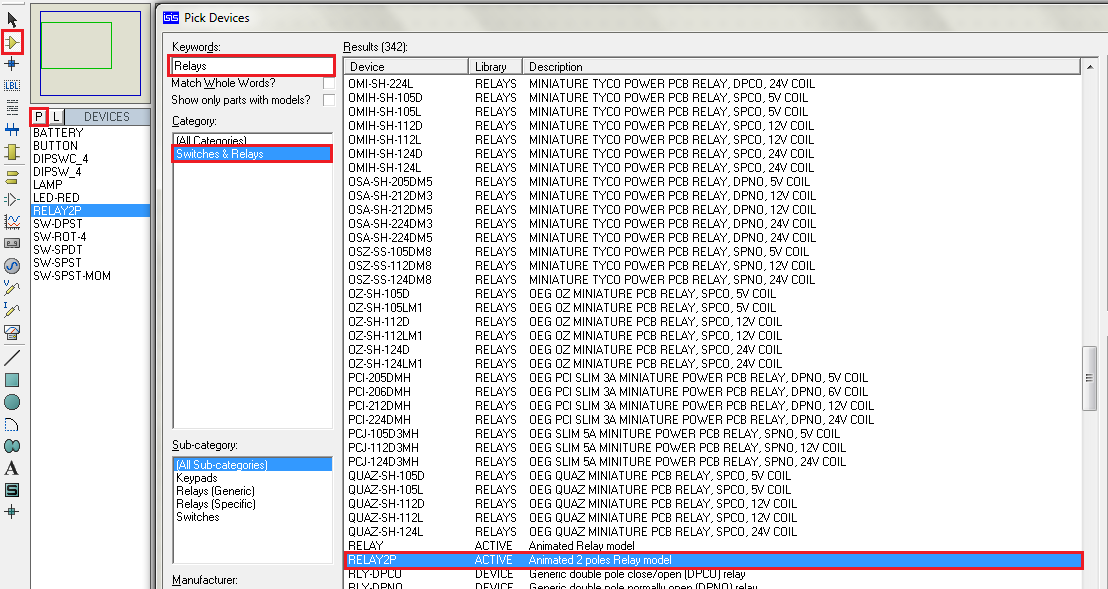
1.9 Relays
Relay is an Electromagnetic/Electromechanical switch operated by a control signal generated by a control circuit or signal given by human. It is generally used in circuits where automatic switching is required depending on the real-time scenario. Example of UPS for computers is easily understood.
The switching sounds heard, when power cut occurs, is made by relays. Also, auto changing of home inverters from Mains to inverter and vice versa.
As an example Relay latching technique is presented as which is mentioned in the Momentary action of switches topic.
The stop switch SW2 should be latched to close position before starting the simulation. Connect the circuit as per the circuit diagram and run the simulation. Momentarily close the SW1 to Latch the relay. The relay remains in ON state even after releasing the SW1. Then open SW2 to Off the relay. This is generally used in Pump motor starter circuits.
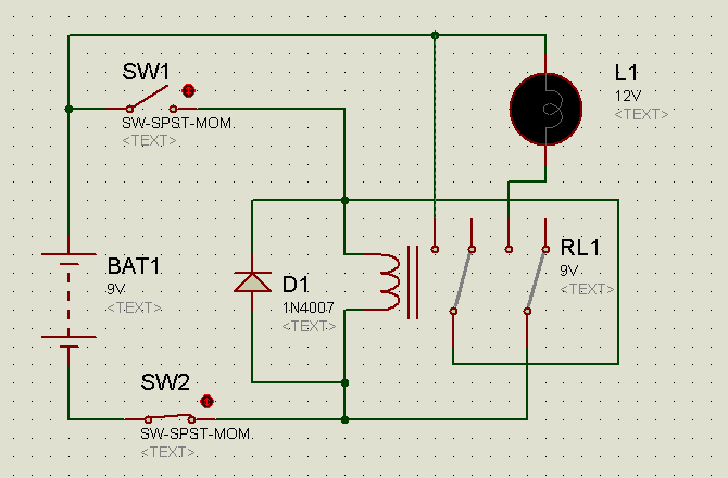
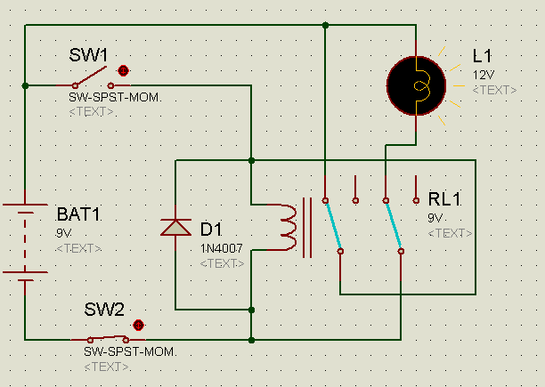
The inductance property of the relay generates high opposite voltage across its terminals when it
is turned OFF, so a free-wheeling diode is place in anti-parallel fashion to it.
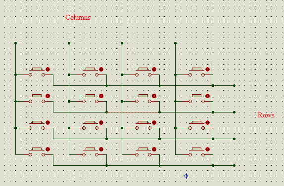
1.10 Matrix Keypad
A number of Push buttons arranged in rows and columns form a matrix keypad. A microcontroller is employed to operate it easily.
1.11 Thumbwheel Switches
These are rotating type digital switches and give output in binary format. They can be used in applications where set points are to be set by the user like alarms or clocks or temperature settings etc..,They replace the push buttons for ease of operation to the user.
A microcontroller is required to read the output. A simple alternate circuit is presented for now, using BCD-Seven segment decoder IC 7448.
1 Comment
i have a doubt about my project.that is my project can be done by using proteus or not.
my project is hybrid motor bike.in this we are converting rotational energy of bike into electrical energy(store that energy in battery) and then we are giving that energy to the wheel like an ebike. it can be done using proteus.then how to do it .