Description.
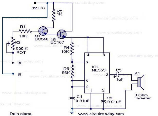
Here is a simple rain alarm circuit that produces an audible alarm when ever rain falls. The rain detector circuit is based on two transistors (Q1 & Q2) and a NE555IC (IC1). The two transistors are wired as a switch which goes on when the base of Q1 is shorted to the positive of the supply by the rainwater falling on the sensor. When the transistors are ON power supply is available to the IC1 which is wired as an astable multivibrator. The output of IC1 drives the speaker to produce an alarm.
Do you need to learn more on the basics of electronics? Are you a student who is not so familiar with the practical side of electronics? If so, CircuitsToday has reviewed and listed 4 books on the basics and practical knowledge in electronics, written by world famous authors like Forrest M Mims, Charles Platt and so on. These books are followed by some major universities all around the world. You can review them, and buy them online by clicking on this link:- 4 GREAT BOOKS TO LEARN BASIC ELECTRONICS.
Circuit diagram with Parts list.
Notes.
- Assemble the circuit on a good quality PCB or common board.
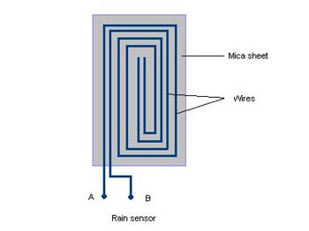
- For assembling the sensor cut a 2×2 inch mica or plastic sheet. Arrange two single stranded wires (running parallel 2mm close to each other) on the sheet as shown in figure below. Remember the wires have to be non-insulated. Sensor ready.
- Now you can connect the points A&B on the sensor to corresponding points A&B on the circuit.
- POT R2 can be used to adjust the sensitivity.
- To test the circuit, make all connections and power up.Place a drop of water on the sensor so that two wires become shorted through water. Now the alarm starts sounding. If not adjust R2 to get the alarm sounding.
- Use a 9v battery or a 9V regulated DC supply for powering the circuit.
- Do not connect speakers less than8 Ohm impedance as load. It will damage the IC.
- A piezo buzzer can be also used instead of the speaker.
Sensor schematic.
Note:- We have recently developed a fully functional Water Level Controller using 8051 Microcontroller. This water level controller monitors the level of the over head tank and automatically switches on the water pump when ever the level goes below a preset limit. You may try the circuit!
63 Comments
I think The Addition Of The Darlington Circuit is a Great Ideal…Here Is Why!! The Total Gain Of The 2 Transistors is Av = hfe1 x hfe2 This Will greatly INCREASE the Sensitivity Of The Circuit and will give an Indication to even a small Amount Of Rain!!! Thank You To The Designer Of This USEFUL CIRCUIT!!!
i think the darlington pair made of BC 548 and BC107 is not nedded.. we can
use only one transistor….. since the sensor sense the rain and provide the voltage to the base of the transistor and this will allow the timer to run…. this will indicate the falling of rain…
what i coming to say is use only one transistor insted of two and the output will be same. use BC548 n-p-n transistor.
and the circuit is good and the sensor that made was superb………..
can you show circuit you prefered ????
hi
i just want to know which sensor is used in the project ?
do reply .
this project is very effective.because i do this circuit practical.
sir..will u send more details and components required with cost tomy mail..
I’m interested in the rain sensor, the milar sheet with the wires.
Do you have any information such as manufacturer, part number, etc. for the possibility of purchase?
Many thansks in advance,
Fernando
Hi sir,I tried this project and initially it doesn’t work but i changed POT value finally I got result.thanx for ur project
sir we r attempting this project fr our 1st yr and hence we are a little bit short on the technical knowledge.it would be of great help if u could send us information about the circuit and the doe’s nd don’t related to it. it would really help us ,please send asap.
thanking u in anticipation
shubham
I don’t know how to send you a schem.
Sufice it to say that the sensor is connected in series resistor divider from 5v to gnd, and the change in resistance input into a voltage comparator TS393C for processing.
I am looking for the sensor itself.
Can you help?
Hey its an interesting project..plz do forward the details of the project as soon as possible.
its not working…. usless circuit.. the current on output is very less. which cant drive speaker..
Hi Chinmay NE555 with 9 volt supply can give minimum 250mA frive. Please check the assembly for mistakes. To isolate link Q2 collector and emitter. You should get good audible tone from tweeter. If ok check Q1 and Q2 connections.
Hi sir, pls may u help send me more details of how this circuit can be locally produced for home use.
What does that have to do with info on the rain sensor?
any chance of a PDS of this circuit or more detail on the components? it would be appreciated.
its really working and interesting,Still more information needed for the project………..
today i am made this rain alarm project its very complicated project in designing or programming methods . my office HR secretory can help me & programming to this project .
I liked your circuit v.much. I shall be very obliged if you send me a detailed information about this circuit. I have just started to study the 555 timer IC. I need a detailed description of this circuit so, I can more clear my concept about 555. My Email is omer.mirza1118@hotmail.com
Sir,, can we modify this circuit to an automatic clothesline, by replacing the tweeter by a motor ? ? ? ?
hi i am ashish butola going to make a minor project on the fire alaram. so i need a lot of help to make this project. so i reque4st to all my engineering frind to help me. i will be a great thankfull of your.
Hi Mustafa IC1 is wired as an astable oscillator running at around 1kHz. Which gets the power from Q1 & Q2 (a high gain super alfa pair)when drain drop bridges the A & B.
Please seetharaman i will be very pleased if you can send a detailed description on the components of this rain alarm circuit for example the function of the transistors and the ne555 because i used it as my mini project and i will deliver the final report next week please send it this email km_nab_ban@yahoo.com
hello seetheraman please i want a replacement for mica with any other material because i didnt find any and how can i home made this rain sensor sheet please send the details to amory_716@yahoo.com
R/Sir
.. . Please provided me full information about this project and its component list.
Regards
Aas mohd
HI plz send me some more information about this topic and how it works plz rply me as soon as possible
hey i need this concept 4 ma miniproject…….will u plz leav sm info on ma id…2day or 2moro itself….plz give appplictions and related all theory wich i need 4 proj,,,,,,plz reply soon……
pls send it on my email add. krizza_gallaza@yahoo.com
thank you
this circuit may be a great help, pls send the other details/informations of this circuit…on how it works?
and can i ask something?
“if you change the value the resistors (any resistor) what is the effect to the circuit?” same with the capacitors?
thank you so much… i need this by nextweek…
your reply is really appreciated…
pls send me the theory of rain alarm.i am 12 class student. thanks guy!
I am Ronit of class 12th. It gives me satisfactory knowledge. Morever that’s the perfect project to me.
Hi Satish and Samson the article is very clear about the operation and the notes gives you other details. there is no need for any other information. If you still have doubts, please ask specific questions it will be answered
Pls this circuit will be of great
help,if you can send the details
to sbgaikwad38@yahoo.com
I’ll be most grateful sir cos its
important for my project.thank
you.
Hi am a final Year of elect/elect pls I lov this project I want you to send the full detailS of this project to. My box and description and the components thanks
Pls this circuit will be of great help,if you can send the details to emma44tou@yahoo.co.uk I’ll be most grateful sir cos its important for my project.thank you.
Hi Rajesh use glass epoxy straight line bread board PCB. use alternate tracks in parallel. use PCB vertically such that tracks are parallel to ground.
hi, I am student of final year,i want to do this rain alarm project as mini project please tell how to make this sensor breifly please reply soon because 25 nov is the last date of submission of the project because this sensor is not availabel in the market. can i use light sensor or any other sesoor ?
pleae ! thanks
nice
ya it is working model
hi,pls snd me al details of rain alarm project….hw it works,
its components name n also describe the details of every components….
its a very interesting circuit….i will try to do this…thank u
Hi jain within INR100.
hiiii,
m student of final year ec,want detail information for the rain alarm project.how much will it cost.please reply me as soon as possible..my id is..
jainaman8@gmail.com
hi please help me.only 1 day is left for the submission of rain alarm project
Hi Neo keep the sensor in an angle so that the water droplets flows out, which will ensure the alarm to get reset soon.
great dude simple and working. but once the water drops on the sensor it is shorted now even if the rain stops its still shorted due to water around.
hi
can you do the PCB layout of the circuit please?!
thank you.
Maximum 8 ohms 2 watts tweeter will do.
Thanks for reply one question is more that is:
please tell me speaker watts value.?
Hi Zubair R1, 3, 4, 5 are 1/4 watt 5%. C1 & 2 are ceramic disc capacitors. R2 Variable pot used as rheostat. C3 is electrolytic capacitor can be 12V Working voltage or more.
I have a question, please tell me the each resistors watts value and which type of capacitors are used and also tell me C3 capacitor volt value.Thanks reply me soon.
today i make rain alarm circuit its working..
Hi Tala till the sensor becomes dry the alarm will not stop. Hi Anil once the water drop bridges the sensor it gives the bias to the emtter follower pair that in turn gives supply to 555 oscillator, which produces the sound.
hi,
question
does the output stop until the rain stops?
Oi, estou com um pouco de dificuldade em encontrar os capacitores de 0,01uf, teria como substituir por um outro?
we have not tried it but it seems interesting
please help and contact me at +919888405485
hiiiiiii.
i want a detailed project report on rain alarm for my +2 board exams.
please help……… please help……………
i tried rain alarm circuit..it is working………..
i tried ur ckt of water alarm.but it is sounding without the droplet.it starts sounding as soon as i plug it.please help.
This circuit requires calibration before use and it can be done adjusting the POT R2.
Hello I want the warning on the car radio
hello, pliz send mi full report on this project because am doin it as my final yr project.thank you
pliz may u reply mi as soon as u read this,i badly need it.send it ledeamoni@yahoo.com