Designing a Spinning/Rotating LED Display
In this project, we are going to show you how to make a simple “Rotating LED Display† (also popularly known as Spinning LED Display) with Arduino. The motivation to make this project came to my mind when I saw a product in the market, in which a text message was clearly visible on a “Rotating LED Strip”.

After that, I planned to make this project myself and Arduino is a good choice to build this spinning led display.
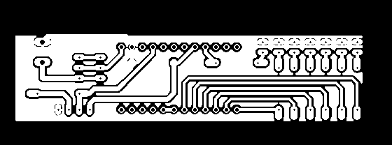
For this project, I designed PCB using Eagle CAD software. The reason to choose Eagle was to build a lightweight PCB, as there is high speed rotation involved in the project, and the PCB will be a part of the rotating module. In this circuit, “Arduino pro mini†is used because it is very small and powerful board.
Seven LED’s, a pair of IR LED and a Photodiode is also used. IR LED and Photo diode are used to design a feedback system; which gives the actual position of the rotor to Arduino. LED’s are placed in a single line and are connected to the Arduino board. A small DC gear motor is used to rotate this circuit; and when the circuit rotates the LED’s make a blink pattern that shows English alphabets. The code can be modified for displaying other languages.
The working of Rotating LED Display is very interesting and it can be used for decoration purpose, where you can make beautiful designs and graphics using this amazing project. This display can also be  used in public places like railway/ bus station and airport as a sign board, as it is very cost effective to build. Proper maintenance is necessary for the gear motor and rotating assembly.
Circuit Diagram

Circuit diagram is shown above. I also designed a PCB on EAGLE and the files are given below. it would be better to use etched PCB. PCB Etching process is a simple task, you can learn this from our blog. For PCB etching refers the figure given below.

If you do not want to etch the PCB, just use the General Purpose PCB (GPP), which is easily available in the market.

As you can see, circuit is simple but here I am explaining some key points that should be kept in mind.
Use Rectangular LED’s; because circular LED’s consume more space, and the layout designed by me is based on rectangular LED’s.
After making the connection, check the IR LED. IR ray is not visible to our eyes, so open the camera of your smart phone and observe the IR LED through your smart phones screen. If light is visible on IR LED, then the connection of LED is fine.
Connection of Photodiode is a little confusing, because Photodiode works in reverse bias. For proper connection just see the figure below.


This circuit can be powered with a 9-volt battery, connect the battery with power connector using battery cap.
After soldering all the components, just switch on the circuit and check the power LED on Arduino. If the LED is glowing, you can upload the code.


| S. No. | Name | Quantity | Value | Specification |
|---|---|---|---|---|
| 1. | Arduino Pro Mini | 1 | ||
| 2. | Copper Clad PCB | 1 | ||
| 3. | DC Geared Motor | 1 | More Then 300 RPM | |
| 4. | Wheel | 1 | For Motor | |
| 5. | Adapter | 1 | 12 V | |
| 6. | Battery | 1 | 9 V | |
| 7. | Battery Cap | 1 | ||
| 8. | LED | 7 | RED, Rectangular | |
| 9. | Resistance | 8 | 330 ohm | |
| 10. | Resistance | 1 | 10K ohm | |
| 11. | IR LED | 1 | ||
| 12. | Photo Diode | 1 | ||
| 13 | DPDT Switch | 1 |
Motor
I am using a 12 volt DC geared BO motor whose RPM is 300. Here I chose BO motor because it is very easy to install. Â You can use another motor based on availability, but do not use very small motors as it cannot carry weight of the circuit. RPM of the motor should be more the 300.


Installation Video
We have created a video demonstrating how to install the setup – say motor wheel assembly, arduino and the led pack pcb.
Program/Code
Arduino Pro Mini can be programmed using FTDI chip, so connect the chip with Arduino, just copy and paste the code and upload.
Before making the motor assembly, check the circuit. For checking, put a white (reflective) paper in front of the IR LED and Photodiode. LED’s start blinking and blinking will stop if we use black (non reflective ) paper.
Photodiode is an analog sensor. So, it is connected to the analog pin A0 of Arduino. This is defined by an integer StartPin. Seven LED’s are connected to 7 pins of Arduino. They are defined by seven integers PIN1 to PIN7.
In the “void setup()†A0 pin is defined as INPUT, and PIN pins are defined as OUTPUT.
In the void loop(), an integer value is defined which is equal to “analogRead†value of StartPin, if the value val is greater than 200 then it goes to internal loop.
In the “if†statement, every alphabet of text is written, followed by Sp();
In the next steps,  function of all the alphabets are defined. For example, void A(), in which the first line is signal(0,1,1,1,1,1,1) – which is the first column of alphabet ‘A’. In the second line, signal(1,0,0,1,0,0,0) – which is the second column of alphabet ‘A’. And in this way all the columns of every alphabets are defined using signal function.
In the end, signal function is defined by void signal where D1 to D7 are defined as HIGH or LOW according to ‘1’ or ‘0’. Following that, a delay of 1 milli second is given. If you are using  a motor of higher speed, decrease the delay.
Demo Video – Working
So here’s a demonstration of how a Rotating LED Display works!
Working of Project
This project is making use of POV (persistence of vision). Suppose we want to show alphabet A, then you can see as in figure given below, at a time LED’s of only one column are blinking.

Initially LED’s of column 1 blinks, and next time column 2 and so on. In the code, delay of some milli seconds should be applied between the blinking of two columns, and in our case it is one millisecond.
This whole scenario (blinking of all columns one by one) makes a complete alphabet. Speed of motor is high enough that our eyes cannot feel the blinking of LED’s (due to persistence of vision).
In the circuit, a pair of IR LED and a Photodiode is also used. When this pair move over the white strip (as shown in figure below), the microcontroller (arduino) identifies this point as the starting position and LED’s start blinking according the text. In this way LED’s blinks in the same pattern all the time, so we can see the text displayed on it.

Troubleshooting
If the led’s are not blinking when white paper is placed in front of  the IR LED and Photo diode, change the value in line 23 of code.
If led’s are blinking when black paper is placed in front of IR LED and PD, change the value in line 23 of code.
Output Photographs


Very Interesting Project…THANKS SOOO MUCH!!!
You have either got not registration or very poor registration.
You need to stabilise the display.
Colin Mitchell
TALKING ELECTRONICS.