Description.
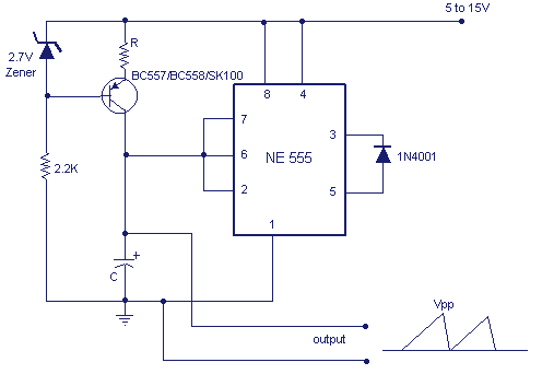
A simple sawtooth wave generator circuit for generating a saw tooth wave form using a NE555 IC is given below. The frequency of the wave form can be varied by using a POT.
The capacitor C, resistor R and zener diode forms a constant current source for charging of the capacitor. When the voltage across capacitor reaches 2/3 Vcc the internal comparator inside 555 goes on and capacitor discharges. When the voltage across the capacitor goes below 1/3 Vcc the internal comparator goes off and now capacitor starts charging. As a result the capacitor will be switched between 2/3 Vcc and 1/3 Vcc, resulting in a sawtooth wave form across the capacitor. The diode make the output voltage to zero during the discharge phase.
Circuit diagram with Parts list.
Notes.
The frequency of the output voltage can be given by the equation,
f = (Vcc-2.7)/(R*C*Vpp).
Where Vcc is the supply voltage and Vpp is the peak voltage of the output required.


8 Comments
POT means potentiometer.. More like a variable resistor
Thankz, this ”article” really helped in my electronics exams…”EEC 244”.
Is 555 timer used is astable or monostable
what is POT??I don’t know what it means….
The output voltage & current of the circuit is too low for my use. i need to amplify the output voltage & current of this circuit. is there any circuit diagram to amplify the output of the circuit?
output voltage can be increased by increasing the supply voltage to 10 or 15V.
If you need to amplify the output voltage you can use a simple transistor amplifier or an opamp.
this circuit works well but i need to increase the discharge time..
hi !!
can u plz help me about how to increase the discharge time of the capacitor and make it bigger than the charging time?