Description.
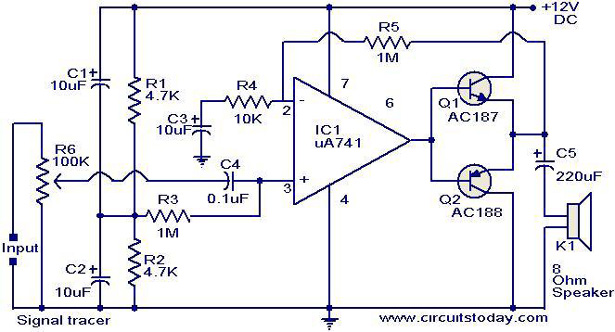
A high gain amplifier circuit that can be operated from a battery pack of 6 or 9 volt battery pack is shown here.The IC1 uA 741 is wired as a high gain non-inverting amplifier and its output is amplified by a pair of complementary transistors (Q1 & Q2) to drive the speaker.The negative feedback from the common emitter junction of the two transistor stabilizes the gain of the circuit.The resulting audio output is sufficient to serve as a signal tracer.
Circuit diagram with Parts list.
Notes.
- Assemble the circuit on a good quality PCB or common board .
- The POT R6 can be used as a volume controller.
- The circuit can be powered from a 6 or 9V DC battery pack.
- The IC1 must be mounted an an IC base.
- All capacitors must be rated at least 15V.
13 Comments
This site very useful every tech. student .And it is easy to understandable.
sir,
I want the whole pdf of this signal tracer with more applications in it ,could u please send me
Hi sir,
i want complete pdf file of this project.could you please send me.
Hi George
3 ohms is too low an impedance for this amp. try with 8 ohms it will be ok. or with 2nos 8 ohms speaker in series it will be still better. ensure output transistors are the recommended germanium matched pair only(this pair requires very low standing current to avoid crossover distortion).
I built the circuit from the picture, and there is one issue to deal with: when I put 60 Ohm headphones, everything sounds good. But when I put 3 Ohm loudspeaker, the distortion is heard from it. I know this is not the right place to ask such question, but what should I do to solve this issue?
its a simple one for learning students to start with.
awesome……Its working…………
wht s d main use of dis circuit………
i need complete information
its really helpful to the students….
hii..
this is rk mishra here..I see this project and obseerve that this is the best from other.