This article is another step forward in learning more about Arduino. In our previous article, I have written in detail about blinking an LED using Arduino. We have demonstrated 5 simple led based projects using arduino, which will help you to learn its basic concepts.
1. Blinking Two LED’s using arduino
2. Control LED using a Push button switch
3. Toggle an LED using Push button switch
4. Toggle 2 LED’s using a Push button switch
1. Blinking Two LED’s using Arduino
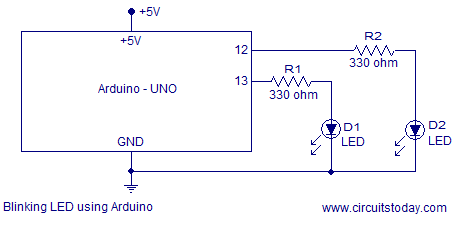
As a beginner, if you have tried the “Hello World” program to blink an LED using Arduino; you can try to blink Two LED’s as next project. There are 14 I/O (input/output) pins in your Arduino uno board. These pins are numbered from 0 to 13. They can be configured as either input or output in the sketch you create for arduino. If you have learned the “Hello World” program carefully, you now know that input/output configuration of pins has to be done inside the setup() function. So here is the circuit diagram to blink 2 led’s using arduino.
Sketch to Blink Two LED’s using Arduino
const int LED1 = 12;
const int LED2 = 13;

void setup()
{
  pinMode(LED1,OUTPUT);
  pinMode(LED2,OUTPUT);
}

void loop()
{
  digitalWrite(LED1,HIGH);
  delay(1000);
  digitalWrite(LED1,LOW);
  digitalWrite(LED2,HIGH);
  delay(1000);
  digitalWrite(LED2,LOW);
}
The only difference in this sketch is use of 2 pins in output mode. I have used pin number 12 and 13 as output. I have configured them as output inside the setup() function. Inside the loop(), I have written commands to blink LED’s alternatively. When LED1 is ON, LED2 will be OFF. After 1 second LED1 will turn OFF and at the same time LED2 will turn ON. Wait another 1 second and you will see LED2 turning OFF and LED1 turning ON. This cycle repeats.
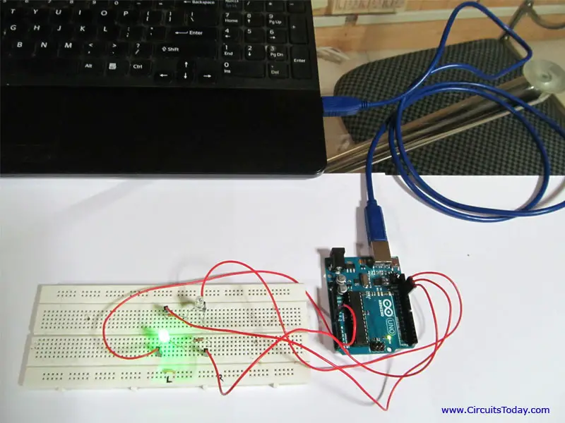
I have added a photograph of the practical setup I made below.
You can watch video of the same circuit below.
2.Control LED with Push Button
If you observe carefully, so far we were just playing with some outputs. We made one LED blink and then we stepped ahead to make two LED’s blink. In both cases we wrote software commands to make our arduino blink led’s automatically at an interval of 1 second. What if we want to control led’s ON and OFF time based on a user input? This means, I want to give an input manually and based on my input LED should turn ON and OFF. We can use a push button switch to give user input to arduino. In fact, we can use any type of a simple switch like Push to On or Push to Off or a mini push button switch. In this example I am using a “normally open” mini push button switch. A normally open push button switch will be in its open state by default. This switch will close for the time we keep its actuator pressed. If you want to know more about working of different push button switches, you can read our detailed article on push button switches.
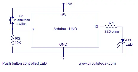
I have added the circuit diagram to control LED with arduino using a push button switch. To connect push button to arduino, we need one of the digital I/O pins configured as a digital input. In this example, I have set pin number 7 as a digital input. So we should connect the push button switch to pin 7 of arduino as shown in circuit. A reference voltage should be connected to one end of switch and the other end of switch should be connected to ground. To avoid a short circuit between pin number 7 and ground, you should connect a resistor (preferable a 10K ohm) in between. The reference voltage is used to detect ON state or closed state of the push button. Arduino board has a readily available +5 volts reference on power pins cluster. When the push button is pressed, the reference voltage line will get connected to pin number 7. This voltage will drop across the 10K ohm resistor. So when push button is pressed, a +5 volts is available at pin 7 and this will be considered as state HIGH. On the other hand, when the push button is released (residing in its normally open state), there is no reference voltage line connected at pin 7. On this state, the voltage across 10K resistor is 0 volts (ground potential). This same potential is at pin 7 as well and will be considered as state LOW. This is how ardunio distinguishes between closed (ON) and open (OFF) states of push button switch.
Lets get into the program side of controlling LED using push button switch. In this program, the highlight is instruction to read push button state. APL (Arduino programming language) has an instruction named digitalRead() – which reads a digital input given at the configured input pin. In our program, this instruction reads the status at pin 7 and returns a value according to what it has read. In our example this instruction reads voltage level at pin number 7; returns HIGH if its +5 volts and returns LOW if its 0 volts. Since it returns a value, we have to assign this instruction to a variable while we write the program. We have used the variable val to store the value returned by the instruction digitalRead(). The push button switch is connected to pin 7 and we have assigned this pin 7 to a variable named SW inside our sketch. Inside the setup() function, we have configured this pin 7 (the SW variable) as input using pinMode() instruction. So here is the program.
const int LED = 13;
const int SW = 7;

 int val=0;

void setup()
{
  pinMode(LED,OUTPUT);
  pinMode(SW, INPUT);
  }

 void loop()
 {
   val=digitalRead(SW);
if(val==HIGH)
{
digitalWrite(LED,HIGH);
}
else
{
  digitalWrite(LED,LOW);
 }
 }
3.Toggle LED using Pushbutton
Lets get into next project which is even more interesting. Here we are going to toggle an LED using a push button switch. Toggle means to change state. Our objective here is turn LED ON with first push button press and turn LED OFF with next push button press. This cycle of ON and OFF should continue with each push button press. The same circuit diagram given above is enough to do this project as we are not manipulating any hardware connection. We just need to change our software (sketch) to change the behavior of this circuit.
Here is the sketch to toggle an LED using push button switch.
const int LED=13;
const int SW=7;
boolean state = true; //declare variable state as boolean
int val=0;

void setup()
{
  pinMode(LED,OUTPUT);
  pinMode(SW,INPUT);
  }
void loop()
{
  val=digitalRead(SW);
  delay(120); // Software debouncing using 120ms delay

if(val==HIGH)

{state=!state; // Compliment variable state using ! operator
  digitalWrite(LED,state);
}
}
I used a “normally open” mini push button switch to implement the circuit. This means a push button press always gives us a “HIGH” state. In other words, we have to sense the closed state of push button switch to turn LED ON and OFF. Turning LED ON and turning LED OFF both depends on a single event – the press on actuator of push button switch (its closed state – when the voltage at switch = HIGH). We can do this program in many ways. An efficient program always will have less lines of code. In this program, I used boolean instructions and a complement operator. In the program a variable named state is declared as boolean and I initialized it as true. You may read more about boolean instruction to get deep idea. A boolean instruction has only two possible values, either true or false. The next highlight of the program is to use of complement operator ( ! ). This is the same negation operator we see in 8051 and other micro controllers. For example, we have an instruction called CPL in 8051 instruction set. This instruction compliments the values in accumulator (0’s with 1 and 1’s with 0’s). In digital electronics, a NOT gate performs the same task.
So here is the working of program. We initialized variable state as true. Other lines of code are the same we used in previous programs. You already know what is written inside setup(). Lets come to loop(). We sense input of switch with digitalRead(SW) and store it in an integer variable val. Now we check for the push button press by continuously checking if the variable val has ever registered a HIGH. If it ever registers a high, we compliment the status of state variable and save it to the same variable. Now if the state variable was TRUE before, it has been complimented to FALSE. We write the status of state variable to LED. Based on the value of state variable LED will turn ON and OFF. LED will turn ON if state variable holds a TRUE and LED will turn OFF if state variable holds a FALSE. This process of reading the push button switch and complimenting the state variable continuous.
Note:- In our program, the first push button press actually turns the LED OFF. It will turn ON only with second push button press. From then it will alternate between ON and OFF with each push button press. If you want it to turn ON with first push button press, you just need to make a change in the boolean declaration statement. Declare the variable as FALSE initially.
Note2:- You might have noted a delay(120); instruction just below the val=digitalRead(SW); instruction. It is called software debouncing technique. This a practical aspect of the circuit. If you are to write the program based on theory, you don’t need a delay instruction here. But there is a practical problem. You may upload the code with out this delay instruction and see the behavior of circuit. Some push button press will actually toggle and some other will not yield an expected result. This behavior is due to 2 reasons. 1) The push button is a mechanical switch. One push button press will yield a series of high pulses (bcz of the vibration created when 2 mechanical parts get in contact) in practice. 2) Arduino is a really fast prototyping platform. In fact its not arduino, its the micro controller used in the board that’s really fast. In an arduino uno, Atmega328 is used which is of 20 MIPS execution capability. This means the controller can execute 20 million instructions per second. It is very very fast than we can imagine. So arduino will sense all these series of high pulses created by one push button press. But we dont need arduino to sense all these pulses. We just need 1 HIGH pulse per push button press. This is a problem created by the bouncing switch and we eliminate this problem through a debouncing technique. There are 2 types of debouncing techniques. Here we apply software debouncing.
4. Toggle 2 LED using Pushbutton
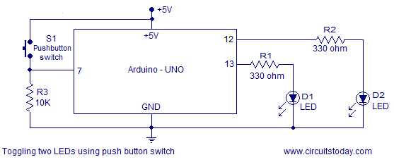
Our next project is to toggle 2 LED’s using a single push button switch. Here we need one more LED and little tweak in the software. I have added the circuit diagram and program below. I respect your intelligence. You don’t need an explanation for this circuit and program after learning this much.
 I have added the sketch below. Read the sketch carefully. We just need to add a few lines to above program. Its really that simple.
const int LED1=13;
const int LED2=12;
const int SW=7;
boolean state = true; // declare variable state as boolean
int val=0;

void setup()
{
  pinMode(LED1,OUTPUT);
  pinMode(LED2,OUTPUT);
  pinMode(SW,INPUT);
 }
void loop()
{
  val=digitalRead(SW);
  delay(100); // Software debouncing

if(val==HIGH)

{state=!state; // Complimenting the status of LED
  digitalWrite(LED1,state);
  digitalWrite(LED2,!state);
}
}
I have added a video of the practically implemented circuit. You can watch it below.
Note 3:- I already wrote that there are different ways to create a program. This same program for toggling LED can be written without using a boolean variable. If we dont use a boolean variable, we can not make use of the compliment operator. This simply means we have to handle the task of switching LED states inside our code. I have added a sketch to toggle an LED without using boolean variable. If you take a closer look, you can see this program is very big and uses more variables and instructions than our previous program (with boolean variable). But both sketches leads the same desired output. So which program is more efficient ? The one with less lines of code!
const int LED1 = 13;
const int LED2 = 12;
const int SW = 7;
 int flag;
 int val=0;
 int state=1;

void setup()
{
  pinMode(LED1,OUTPUT);
  pinMode(LED2,OUTPUT);
  pinMode(SW, INPUT);
  }

 void loop()
 {
 val=digitalRead(SW);
 delay(100);
 if(val==HIGH&&state==1)
 {
   digitalWrite(LED1,HIGH);
   digitalWrite(LED2,LOW);
   flag=0;
 }
 if(val==LOW&&flag==0)
 {
 digitalWrite(LED1,HIGH);
   digitalWrite(LED2,LOW);
   state=0;
 }
 if(val==HIGH&&state==0)
 {
   digitalWrite(LED1,LOW);
   digitalWrite(LED2,HIGH);
   flag=1;
 }
 if(val==LOW&&flag==1)
 {
     digitalWrite(LED1,LOW);
   digitalWrite(LED2,HIGH);
   state=1;
 }
 }
I will explain the code later. Ask in comments if you have any doubts.


6 Comments
iwant to program an ic for sine wave invertor,can you send the programe for this , I am do’nt know to write the programming language . is any way to convert to written program in simple english to the computer language?
for Toggle 2 LED using Pushbutton, what if there lednya number 12?
Hi there, I’ve been reading about arduino boards and I’ve been trying to connect two switches to one LED in a similar way a three-way switch operates. Now I’ve stayed up all night searching for something like. My ultimate goal is home automation. But since I have no clue about arduino, I am going to take it step-by-step.
I read your tutorial and it seems quite easy to do. I’ll be buying an arduino board soon and before I blow it up, I just wanted to confirm whether my idea for this two way switch will work.
It is based on your tutorial of how to toggle an LED using a pushbutton. I have modified the code just a ad bit to allow for the read of two push buttons from different inputs, but giving the same output of changing the LED’s state.
As for the circuit diagram, I have just added another pushbutton switch in parallel to the first. Do let me know if the code will work or if there are any changes I need to make.
TWO WAY SWITCH CODE:-
const int LED=13;
const int SW1=7;
const int SW2=8;
boolean state = true; //declare variable state as boolean
int val=0;
void setup()
{
pinMode(LED,OUTPUT);
pinMode(SW1,INPUT);
pinMode(SW2,INPUT);
}
void loop()
{
val=digitalRead(SW1);
val=digitalRead(SW2);
delay(120); // Software debouncing using 120ms delay
if(val==HIGH)
{state=!state; // Compliment variable state using ! operator
digitalWrite(LED,state);
}
}