Description.
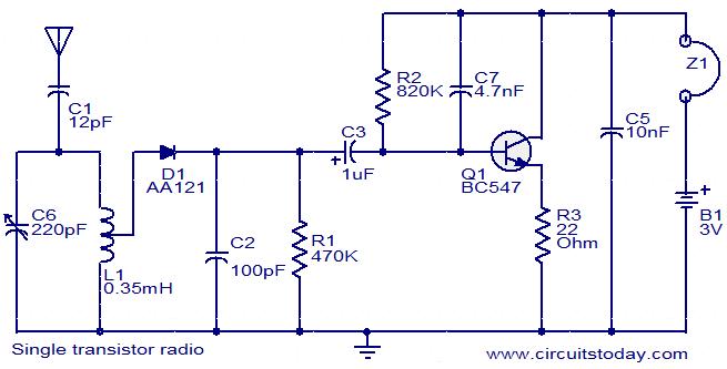
Here is the circuit diagram of a simple radio that uses one transistor and few other passive components.The C6 and L1 forms a tank circuit which picks up the signal from your desired radio station.Diode D1, capacitor C2 and resistor R1 does the detection of the picked signal.The detected signal is coupled to the base of Q1 through capacitor C3.The Q1 gives required amplification to the signal.The resistor R2 is used to bias Q1.R3 limits the collector current of Q1.The audio output will be available at the collector of Q1 and it can be heard by using a high impedance head phone.This radio will work only at places where there is reasonable radio signal strength.
Circuit diagram with Parts list.
Notes.
- Assemble the circuit on a general purpose PCB.
- The circuit can be powered from a 3V battery.
- The antenna can be a 1 M long wire.
- The headphone must be a high impedance(2 to 3K) type.
- If diode AA121 is not available you can use AA112, AA116 or 1N34.
- The inductor L1 must be a 0.35mH, center tapped one.
- The radio can be tuned by adjusting the variable capacitor C6.


27 Comments
is this a circuit with 15 components?
plz someone tell the specifications of inductor coil.
what tank circuit should i use to get 88-108mhz. (pls suggest commercial range)
Hi gays,
Am looking for some one to be my electronic tutor.
here is my personal email to make it easier:butucavieira@yahoo.com.br
Thanks,
can u please help me out and tell me where is capacitor no. 4?
Hi Pranjal there is no C4(not used)
kya ye radio kam karta hai? Kisi ne banaya hai??
can i use speakers in here?
hi… im kinda into this now since i used this circuit for my project..
i have a question.. how can i make adjustments for the volume?? like using a potentiometer to decrease or increase the intensity of the sound.. or is it possible??
sorry im just a student and need your advice.. thank you..!!
Hi bebe there in no need for volume control as the sound will be just sufficient. If you feel it is too loud then replace 470K with a potentiometer and connect slider of the potentiometer to C3.
thank you very much for the reply Seetharaman..
my next question is: is there a possibility to decrease inductor L1 like in micro henries because it turns out that i have to make a 121-turn inductor with 22AWG wire and a 20mm dia coil..?? which i think i will have a hard time doing it..
another is: what kind of antenna should i use??
thank you very much and sorry for being such an annoyance…
Hello, I’ll use a 135nH coil, whith a variable capacitor from 16pF to 30pF, this way I can listen to FM.
Hi Tutu Here L1 is fixed and C1 is variable. You can make L1 variable and C1 fixed. Wind 77 turns of 28SWG super enameled wire on 10mm dia plastic former (100 PVC pipe will do) with a slider to travel on the winding and use a fixed capacitor 22PF as C1.
In the case of C6 and L1 which are both variable components, what happens if you fixed component on either of them?
Hi Val the antenna is a low impedance device. the detector is a medium impedance device to match them the coil is used with the tap. antenna low impedance is taken care by a small value antenna coupling capacitor 12PF. If the coil is damped with low impedance devices the gain will fall and the tuning also will become broad – selectivity will get affected.
Hi John,
could you please explain, why the tank coil has a tap to be connected to the amp circuit? Is it some sort of impedance adoption? How is the translation ratio defined?
Thank you very much.
Original Comment in Croatian: uređaj kupi radio valove od dugog kratkog srednjeg i ultra kratkog vala. uređaj je univerzalne namjene
Translation in English: unit buys radio waves of medium and long-short ultra-short wave. device is a universal purpose
Is this a AM or FM receiver?
Please tell me.
AM, the tank circuit has an ressonance value of 500KHz (arround).
Sorry for bad English.
Hi Raman upto R1 is the radio portion(crystal radio) after that is a simple single transistor audio amplifier. Better to be with the shown values after assembling getting result you can try by changing the components if you are sure of your value.
may i now the proper working of this single transistor radio……….plz help me i have to make a project…. wat happn if we change the values of capacitors and resistots
What about the frequency? And its range
can you help me in making the 0.35mH inductor.
please give me the instructions.
@ Mubarak
Try this link https://www.circuitstoday.com/how-to-make-an-air-core-inductor
can we implement on breadboard n n what is the range 4 input signal………..