Description.
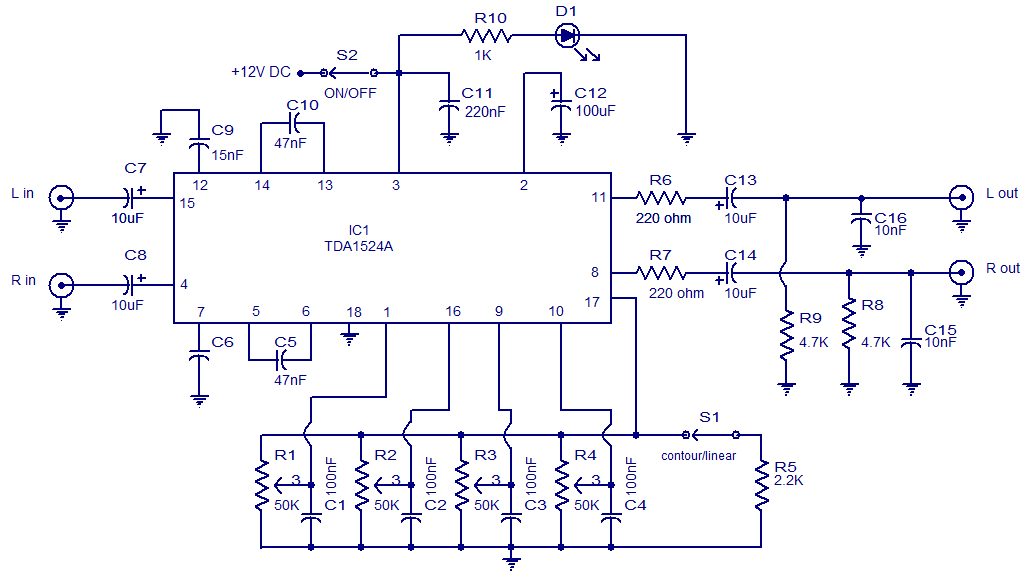
Here is the circuit diagram of an excellent stereo preamplifier with tone control using the IC TDA1524 from Phillips. The IC requires very few external components, has very low noise and has a wide power supply voltage range. POTs R1 to R4 can be used for controlling the volume, balance, bass and treble respectively. LED is D1 is a power ON indicator and R1o is its current limiting resistor.
Circuit diagram.
Notes.
- Assemble the circuit on a good quality PCB.
- Switch S2 is the ON/OFF switch.
- Swich S1 can be used to select linear or contour mode.
- Supply voltage can be anything between 8 to 16V .Here I used 12V DC.


27 Comments
CAN I use THIS PREAMP CKT FOR AUDIO CD
C6 is 15nF.
What is the value of C6 at pin 7
sir
On this circuit you not write capiter (C1 to C16)volt value you must be write and send me parfect circuit.
THANKSSSSSSSSSSSSSSSSSSSSSS
can i use transformator 3 Amp…?
help me please
we can be used in 3 pin pot, but how much working left & right channal
hi,
this circuit use in single pot
What is the output impedence of this preamplifier
question,do you merge the signal,control the tone,and then split the sig,again?
The controls are electronic controls each control will operate for both channels in tandem. Hi Vinu to avoid 1 pot for balance control R2 you have to use 2pots in the input to control the volume. more component count?
Hi,
This is a good circuit. And i want to make this. But i don’t want the balance control . So how can i avoid that pot ?. I know that all i have to connect the in and out without the pot, but the 100nF cap is confusing me.
Which the ic use for this pre amp.?
Tda1524a? Tda1524?
Hello. Sir.
I am grade 10 student.
47nf polyester’ku pathila etha paavikkalam. Plz.!!
Hi it is 0.015uF (15nF)
Hi Seetharaman what is the value of C6
Hi Anil I have assembled this way back in early 90s a nice circuit with very good quality and control range, with Philips application 40 watt circuit. This circuit is with single supply, hence you can use with single supply power amplifier. motional feed back amplifier is most suited for this chip. Do not try to use this dual supply power amplifiers you will end up with heavy distortion of reproduced sound.
is this circuit is tested by anyone?????? It is working properly????
does anyone know what is the rating of the speakers to be used? thanks a lot 🙂
Hi Kristijan R1 is volume, R2 is Balance, R3 is Bass control and R4 is treble control.
admin please can you tell me what pot is for treble,bass,volume…
Hi admin, can you help me finding or combining the schematic of CREATIVE subwoofer which consists of ICs (TDA8510J and MC4558CN) I’m interested in its sound and BASS ,please help.
Hi ADMIN
subject: 100watt sub-woofer
seethraman told me to short R9 & R10 i shorted,temperature of transistors decreased but Q7 is getting hotter than Q5 why ?
where is Seetharaman?
Where is going the other end of S2?And what is the value of C11 and C12(and voltage) capacitors?
My mistake I have added the missing value on the diagram. Pls have a look
What is the value of capacitors C11 and C12? it was not mentioned in the circuit diagram.
Thanks.
Error from my part. I have added the missing values on the diagram. Pls have a look
abook circuit radio puls abook tranmitter fm am