Simple temperature logger using arduino (°C & °F).
This project is about a simple USB temperature logging system using arduino uno and the serial monitor function in the arduino IDE. The system monitors the temperature every 2 seconds and shows it on the arduino serial monitor. The temperature is shown in °Celsius and °Fahrenheit. The system is interfaced to the PC through the USB port. LM35 is used as the temperature sensor.
LM35 is three terminal linear temperature sensor from National semiconductors. It can measure temperature from-55c to +150C. The voltage output of the LM35 increases 10mV per degree Celsius rise in temperature. LM35 can be operated from a 5V supply and the stand by current is less than 60uA. The pin out of LM35 is shown in the figure below.
Circuit diagram. 
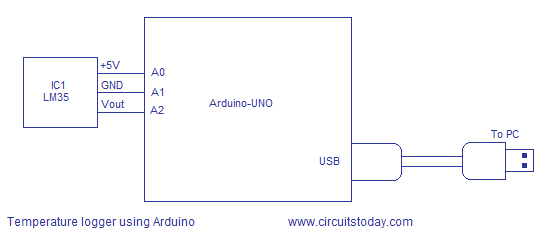
Temperature sensor LM35 is interfaced to the Arduino through the analog input pins A0, A1 and A2. Analog input pin A0 is made high and it acts as the 5V supply pin for the LM35. Analog input pin A2 is made low and it acts as the ground pin for the LM35. Analog input pin A1 is set as an input and the voltage output of LM35 is coupled to the arduino through this pin. This scheme is very useful because you can plug the LM35 directly into the analog input female connector and no external connection wires are needed. The arduino board is powered by the PC through the USB cable and no external power supply is needed in this circuit. The USB port also serves as the medium for communication between arduino and PC.
Program.
int t=0;
int vcc=A0; // sets analog input A0 as +5V source for LM35
int sensor=A1; // sets A1 as the sensor input
int gnd=A2; // sets analog input A2 as ground for LM35
float temp;
float tempc;
float tempf;
void setup()
{
  pinMode(vcc,OUTPUT);
  pinMode(gnd,OUTPUT);
  pinMode(sensor,INPUT);
  digitalWrite(vcc,HIGH); // sets analog input A0 HIGH
  digitalWrite(gnd,LOW);  // sets analog input A2 LOW
  Serial.begin(9600);     // sets the baud rate at 9600

}
void loop()
{ delay(2000); // calls a 2 second delay
  t=t+2;       // increments the time by 2 every two seconds
  temp=analogRead(sensor); // reads the LM35 output
  tempc=(temp*5)/10;       // converts the digital value into temperature degree C
  tempf=(tempc*1.8)+32;    // converts degree C to degree F
  Serial.println("...............");
  Serial.println("Temperature logger");
  Serial.print("Time in sec = ");  // prints the time on serial monitor window
  Serial.println(t);
  Serial.print("Temperature in deg C = "); // prints the temperature in degreeC
  Serial.println(tempc);
  Serial.print("Temperature in deg F = "); // prints the temperature in degreeF
  Serial.println(tempf);
}
About the program.
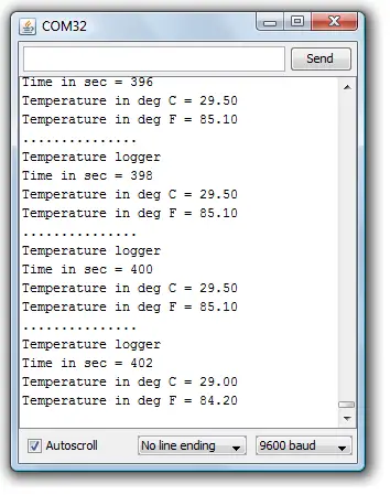
The voltage output of LM35 is connected to the analog input A1 of the arduino. The voltage at this pin will be proportional to the temperature and this voltage is read using analogRead function. The analogRead function will read the voltage (in a range 0 to 5) at a particular analog input pin and converts it into a digital value between 0 and 1023. For example, if 29°C is the temperature, the output of LM35 will be 290mV. The result of the analogRead function will be 290mV/(5/1023) =59. There must be some way to convert this 59 to 29.0 for displaying in the serial monitor window. This is done by multiplying 59 by 5 and then dividing the result by 10. The result will be the temperature in °C and it is displayed using Serial.print function. Then it is converted to °F using the following formula: °F= (°C*1.8)+32. The temperature in °F is also displayed. The serial monitor can be accessed from the Tools tab in the arduino IDE. The shortcut for serial monitor is ctrl+shift+M. The snapshot of the serial monitor window is shown in the figure below.


7 Comments
Using a processor output pin for the LM35’s supply is fine (the precise value of the voltage is not important), but using a signal pin for ground is a bit problematical. The pin may not be driven precisely to zero volts, and whatever voltage is there will add to the output of the LM35, making the reading incorrect by some unknown amount. Even worse, the non-zero voltage on a signal pin can vary depending on the temperature of the chip, and even from one device to another.
Isaac
@Isaac
We did this way for the ease of connection (just to avoid a breadboard). For demo purposes or educational purposes, this approach is fine. In addition it teaches the possibility of using digitalWrite function on an Analog pin. When it comes to real world implementation, we are of your opinion. We always recommend to use the proper GND pin of Arduino to connect LM35’s ground.
Thanks for the comment.
Nice tutorial! 🙂
Hi.
It looks like you have mixed the GND with the Vout pin of the LM35 on the circuit diagram.
Cheers!